Oscilloscope: comparing two signals
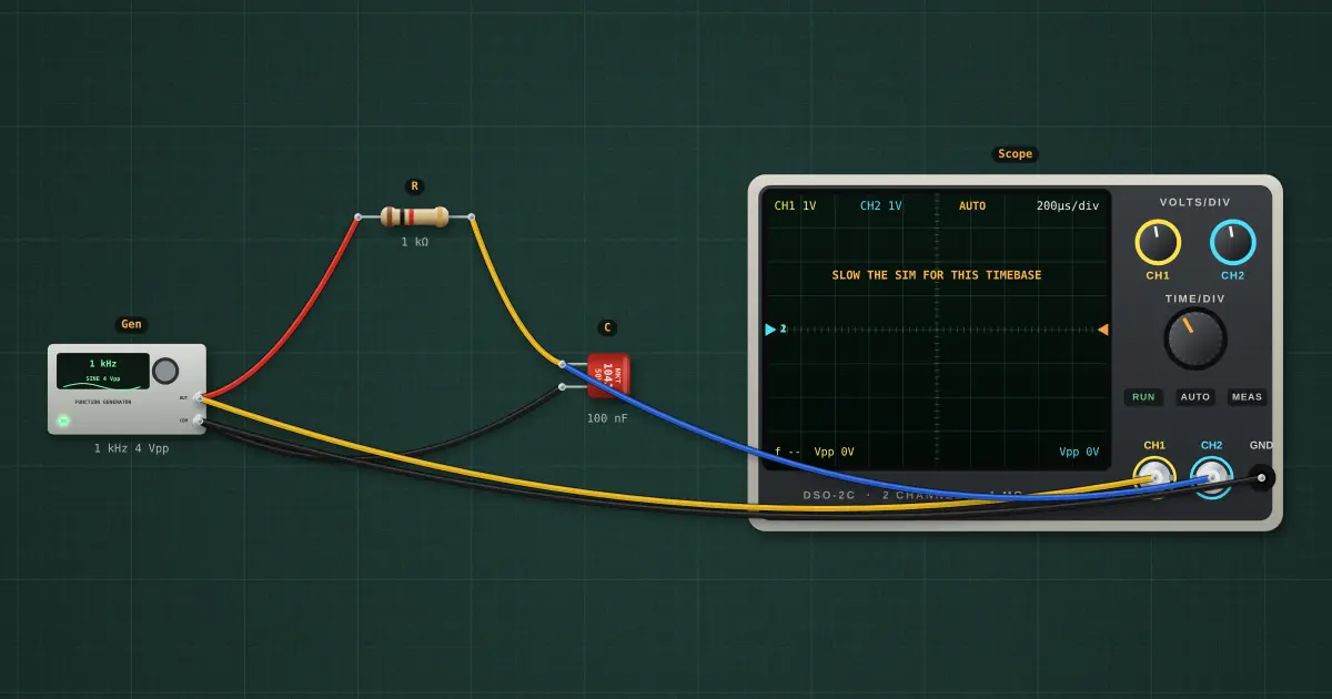
With two channels you can compare a signal before and after a circuit. Here a 1 kΩ / 100 nF low-pass filter is driven at 1 kHz: CH1 (yellow) is the input, CH2 (blue) is the output. The output is smaller and arrives later. Measure the height ratio for the gain, and the time shift between matching points for the phase.
Open this lesson in the labFree, in your browser, no account needed.
How it works
Corner frequency fc = 1 ÷ (2π R C) = 1.592 kHz
Gain = height of CH2 ÷ height of CH1 = 1 ÷ √(1 + (f/fc)²) = 0.847, so CH2 is about 3.34 V peak-to-peak. (CH1 itself is 3.94 V, a little under the generator’s 4 V, because the generator has 50 Ω inside.)
Phase = −arctan(f/fc) = -32.1°. On screen that is a time delay: Δt = (phase ÷ 360°) × T = 89.3 µs, about 0.4 divisions at this time/div. Measure from where CH1 crosses zero going up to where CH2 does.
To read small delays, turn TIME/DIV down until one cycle fills most of the screen, or use the cursors in Tools → Scope window.
Try it on the bench
- Set the generator to 160 Hz: CH2 is almost the same height and nearly on top of CH1. At low frequency the filter passes.
- Set it to 1.6 kHz (the corner): CH2 is 0.707 of CH1 and 45° (one eighth of a cycle) behind.
- Set it to 10 kHz: CH2 is a small wave almost a quarter of a cycle behind. Turn CH2 VOLTS/DIV down to see it properly.
- Switch the generator to a square wave at 500 Hz: CH2 shows the capacitor charging and discharging. The curve is the RC time constant τ = R × C.
- Swap the trigger source to CH2 in the scope settings: now the output stays still and the input moves.
Parts on the bench
In the course
Zen’s Electronics Design Mastery, module “AC & Reactance”.