Bench builds
66 complete gadgets. Each has a parts list, a guided build, a test sheet with pass ranges, and fault-finding practice.
Batteries and solar
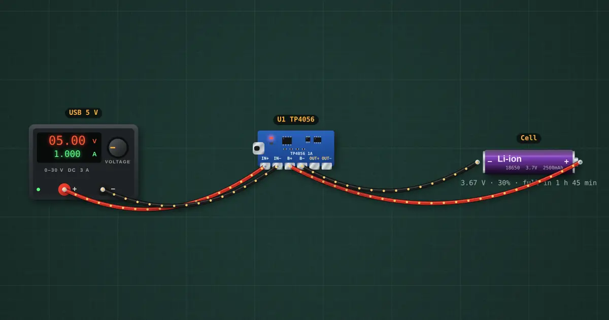
Single 18650 charger with LED charge indicator
Charges one cell from USB; red while charging, blue when full.
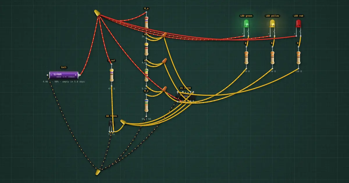
18650 battery level indicator
Three LEDs show full, half and low.
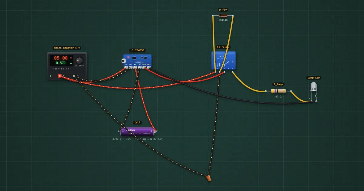
Automatic emergency light
LED lamp turns on when mains fails, charges when it returns.
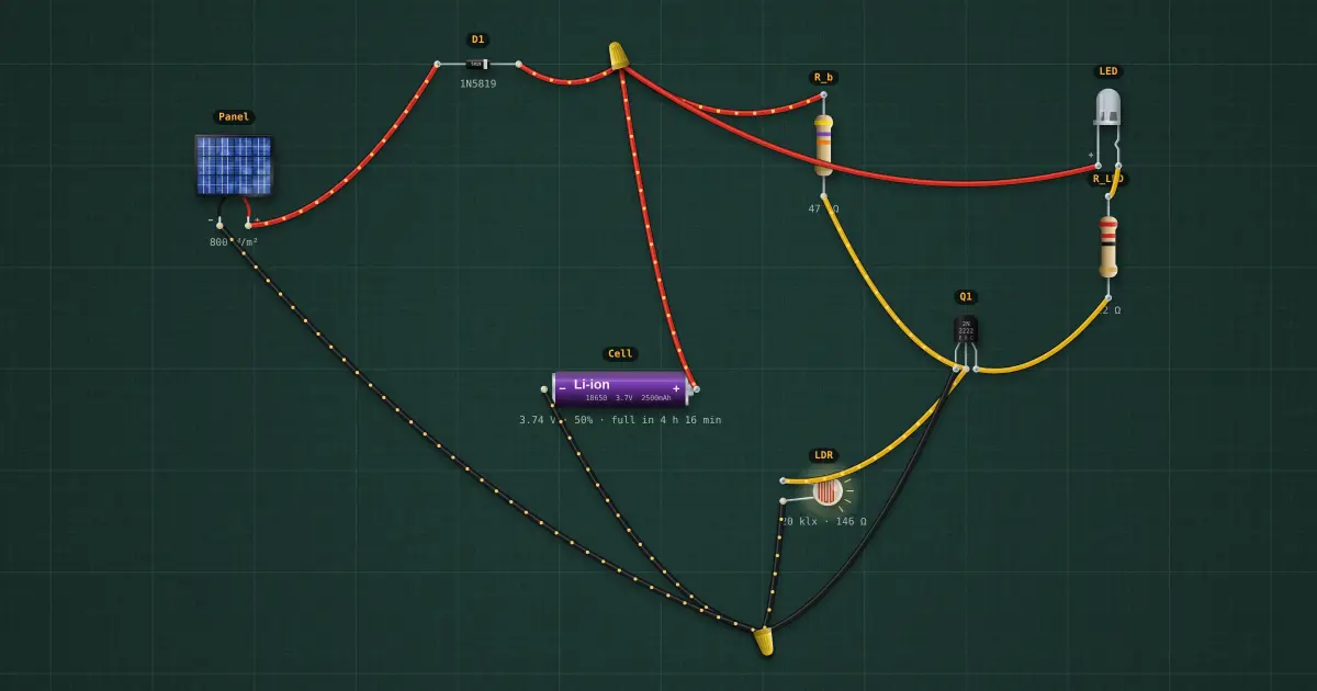
Solar garden light with dusk switch
Charges by day, lights at night.
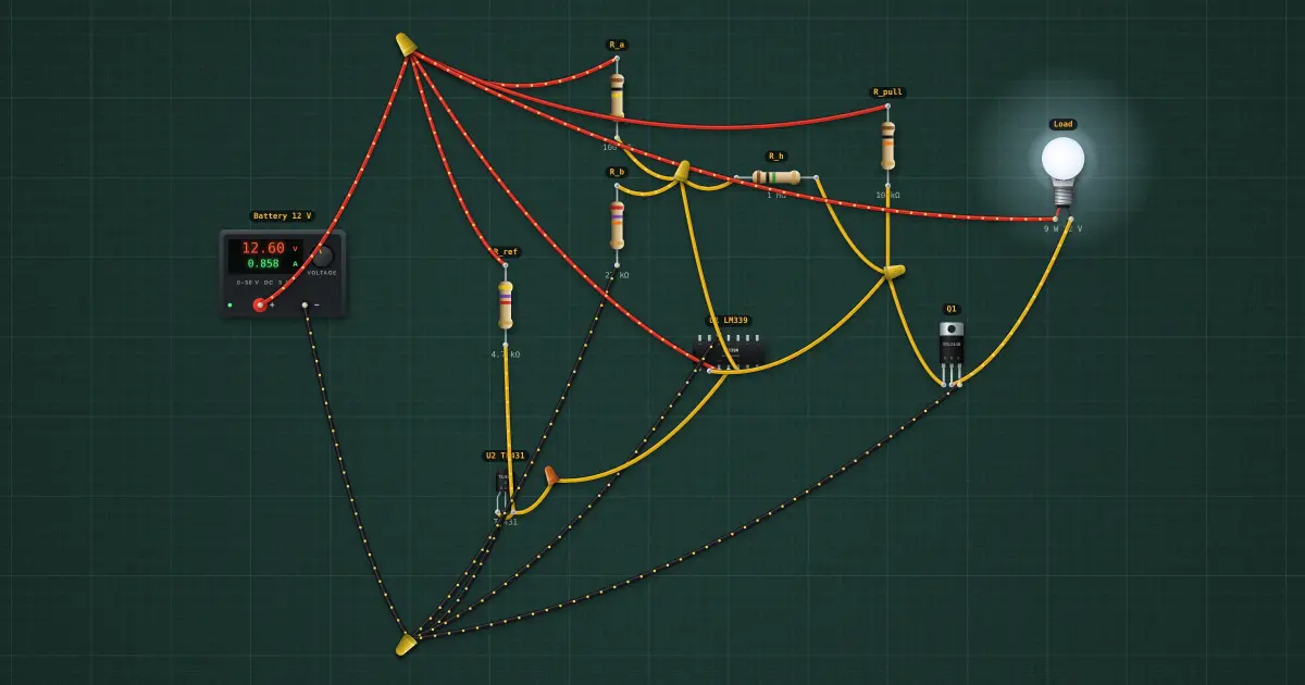
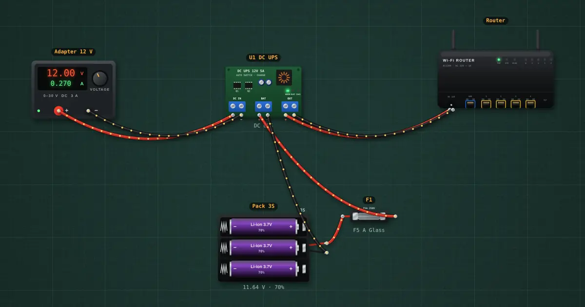
12 V low-voltage battery cutoff
Disconnects the load before the battery is damaged.
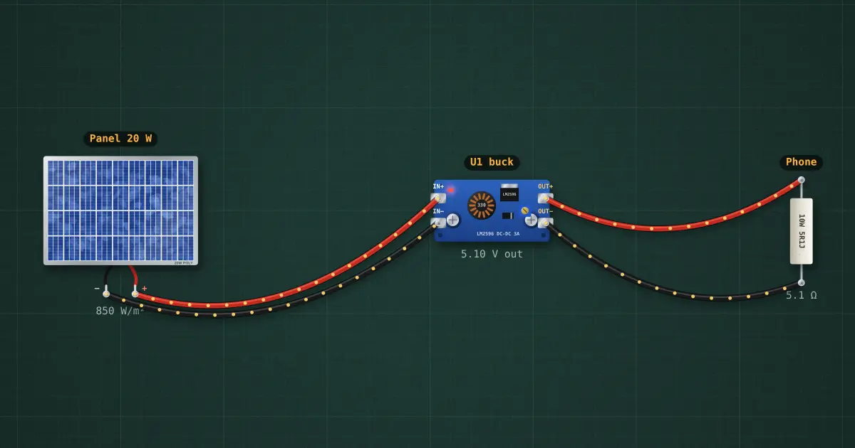
Solar phone charger
Panel to USB with a buck converter.
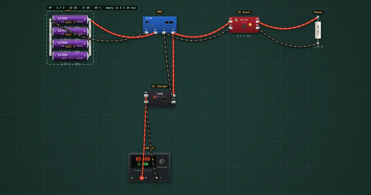
10,000 mAh power bank · 4 × 18650
10,000 mAh, 5 V 2.4 A USB out, 2 A USB charging, full protection.
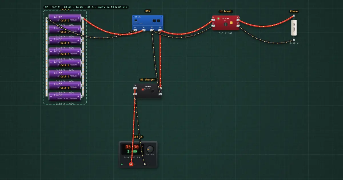
20,000 mAh power bank · 8 × 18650
20,000 mAh, 5 V 2.4 A USB out, 2 A USB charging, full protection.
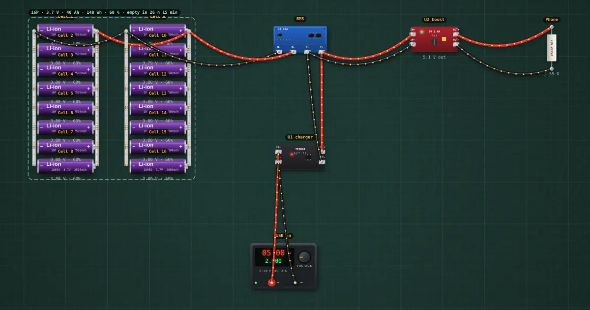
40,000 mAh power bank · 16 × 18650
40,000 mAh, 5 V 2.4 A USB out, 2 A USB charging, full protection.
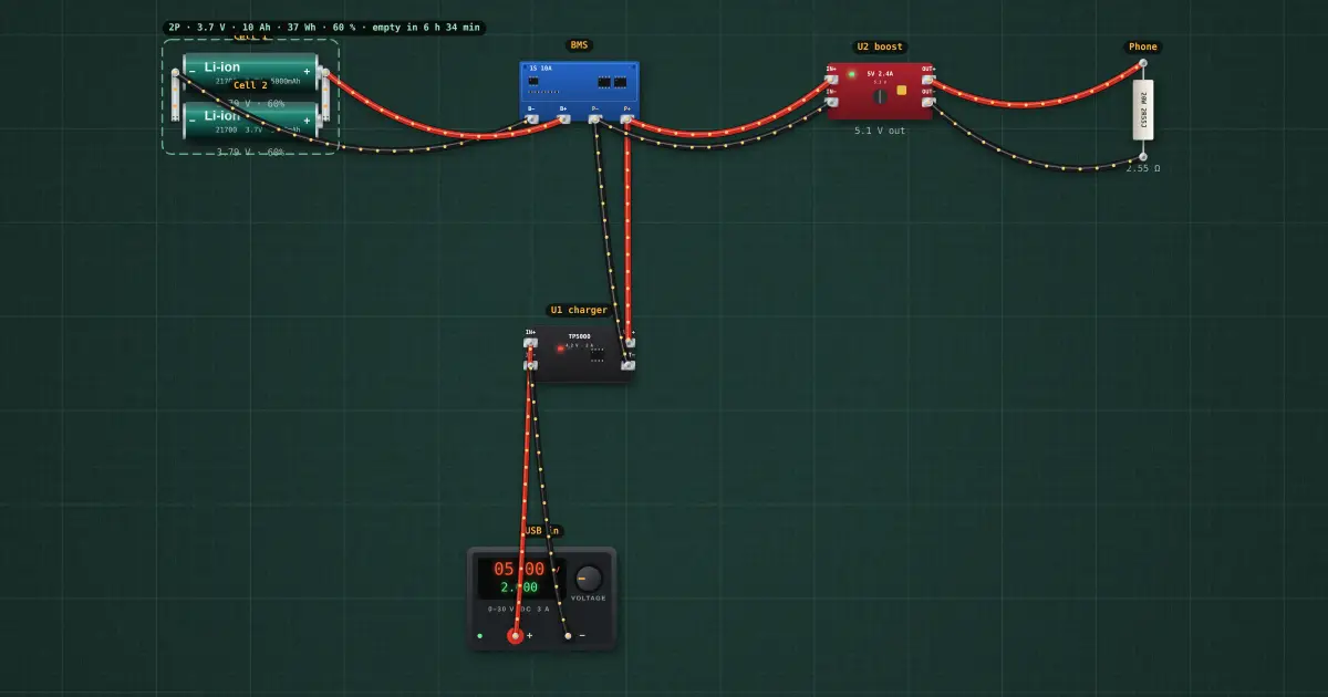
10,000 mAh power bank · 2 × 21700
10,000 mAh, 5 V 2.4 A USB out, 2 A USB charging, full protection.
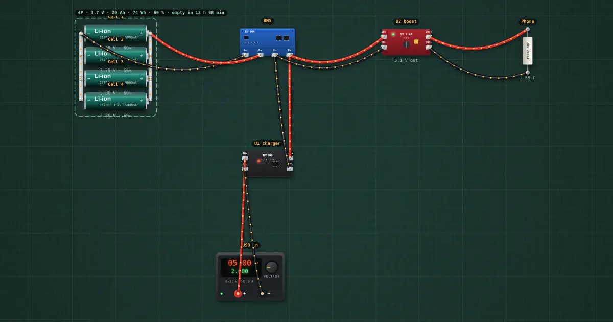
20,000 mAh power bank · 4 × 21700
20,000 mAh, 5 V 2.4 A USB out, 2 A USB charging, full protection.
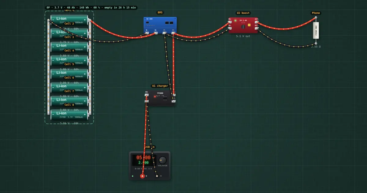
40,000 mAh power bank · 8 × 21700
40,000 mAh, 5 V 2.4 A USB out, 2 A USB charging, full protection.
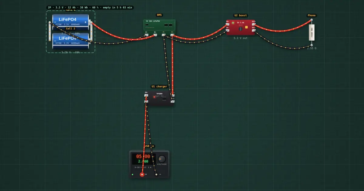
12,000 mAh LiFePO4 power bank · 2 × 32700
12,000 mAh, 5 V 2.4 A USB out, 2 A USB charging, full protection.
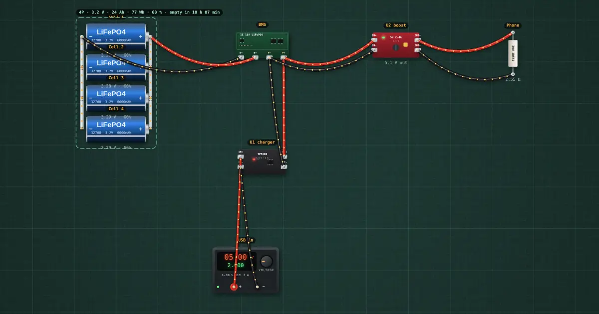
24,000 mAh LiFePO4 power bank · 4 × 32700
24,000 mAh, 5 V 2.4 A USB out, 2 A USB charging, full protection.
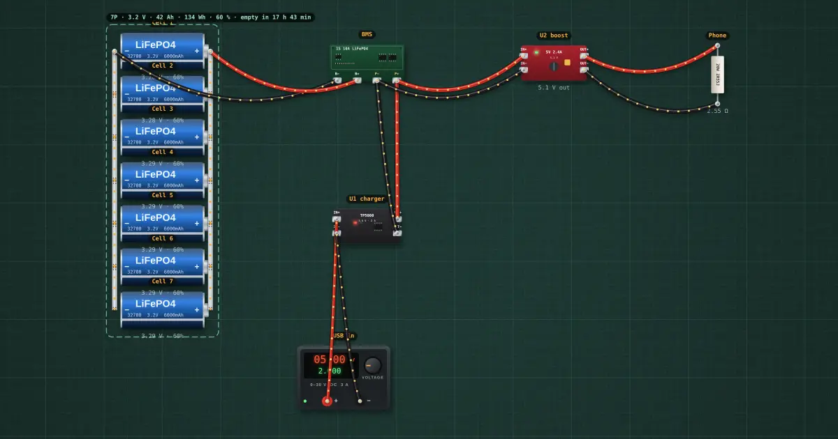
42,000 mAh LiFePO4 power bank · 7 × 32700
42,000 mAh, 5 V 2.4 A USB out, 2 A USB charging, full protection.
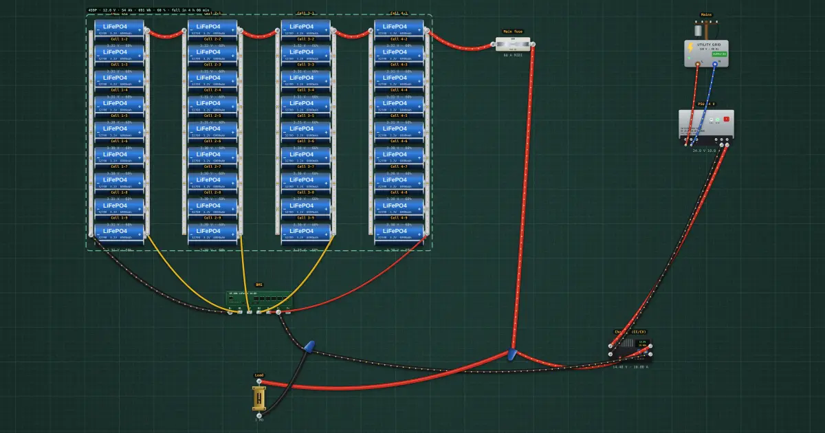
50 Ah 12 V LiFePO4 battery (4S9P, 32700 cells) with charger
12.8 V 54 Ah (691 Wh) battery from 36 × 32700 cells, 4S BMS with balancing, 10 A CC/CV charger from mains.
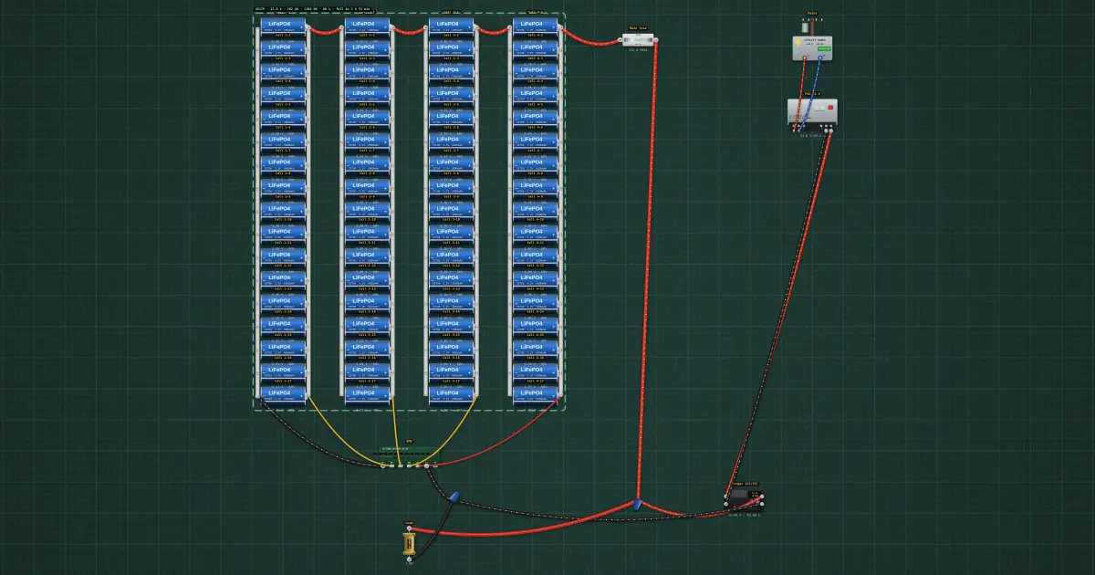
100 Ah 12 V LiFePO4 battery (4S17P, 32700 cells) with charger
12.8 V 102 Ah (1306 Wh) battery from 68 × 32700 cells, 4S BMS with balancing, 20 A CC/CV charger from mains.
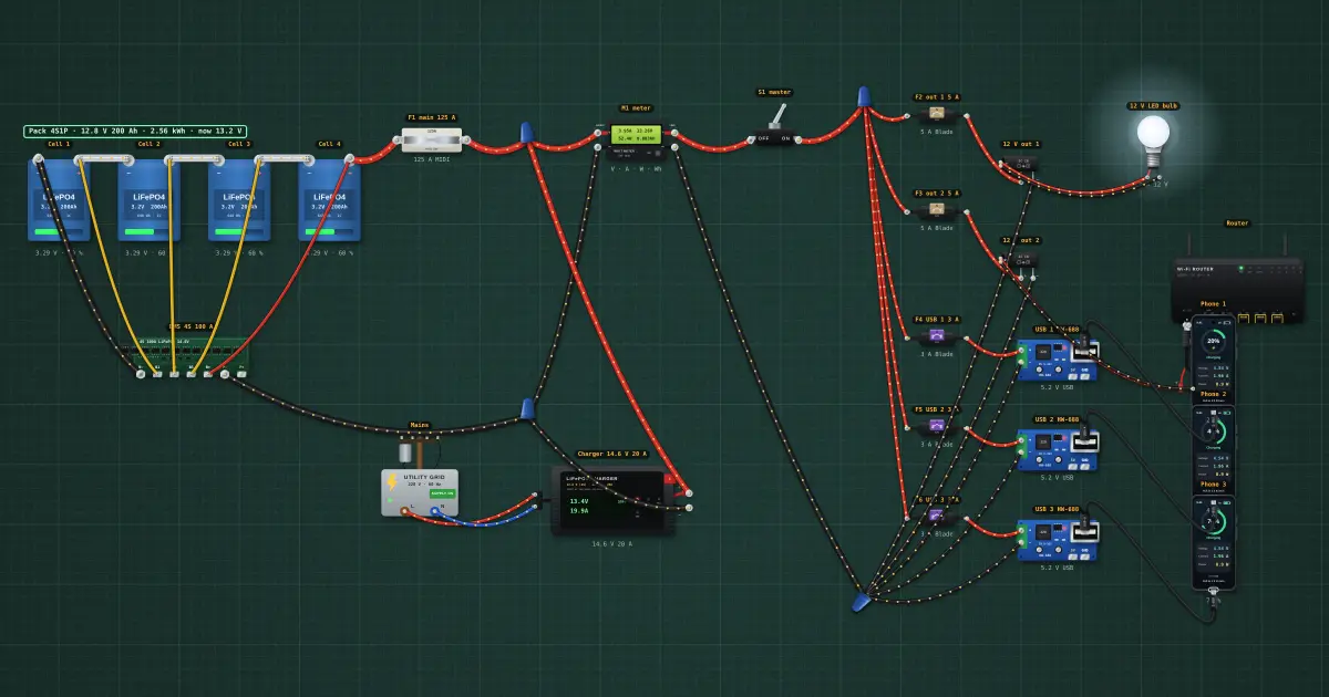
200 Ah power station from four 3.2 V prismatic LiFePO4 cells: 4S BMS, 2 × 12 V, 3 × USB, mains charger
12.8 V 200 Ah (2560 Wh) power station from four prismatic cells with a 4S BMS, two fused 12 V outputs, three USB…
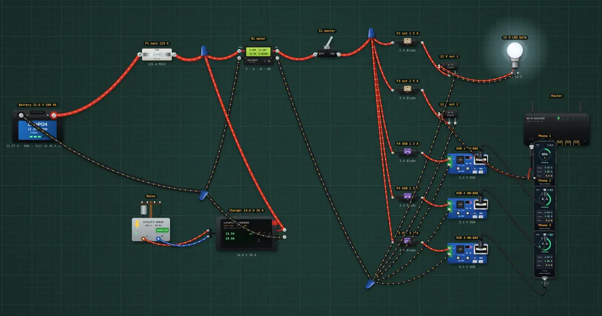
200 Ah power station on a 12.8 V LiFePO4 battery: 2 × 12 V, 3 × USB, mains charger
12.8 V 200 Ah (2560 Wh) power station on a drop-in battery, two fused 12 V outputs, three USB outputs, a watt meter…
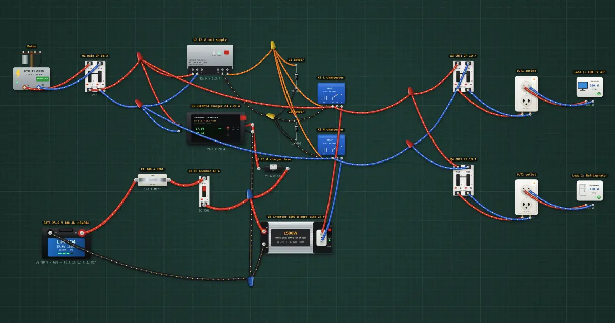
Home UPS on a 24 V LiFePO4 battery: charger, inverter, changeover relays, two 220 V outputs
Keeps two 220 V circuits powered through outages from a 24 V LiFePO4 battery; charges from the grid when it returns.
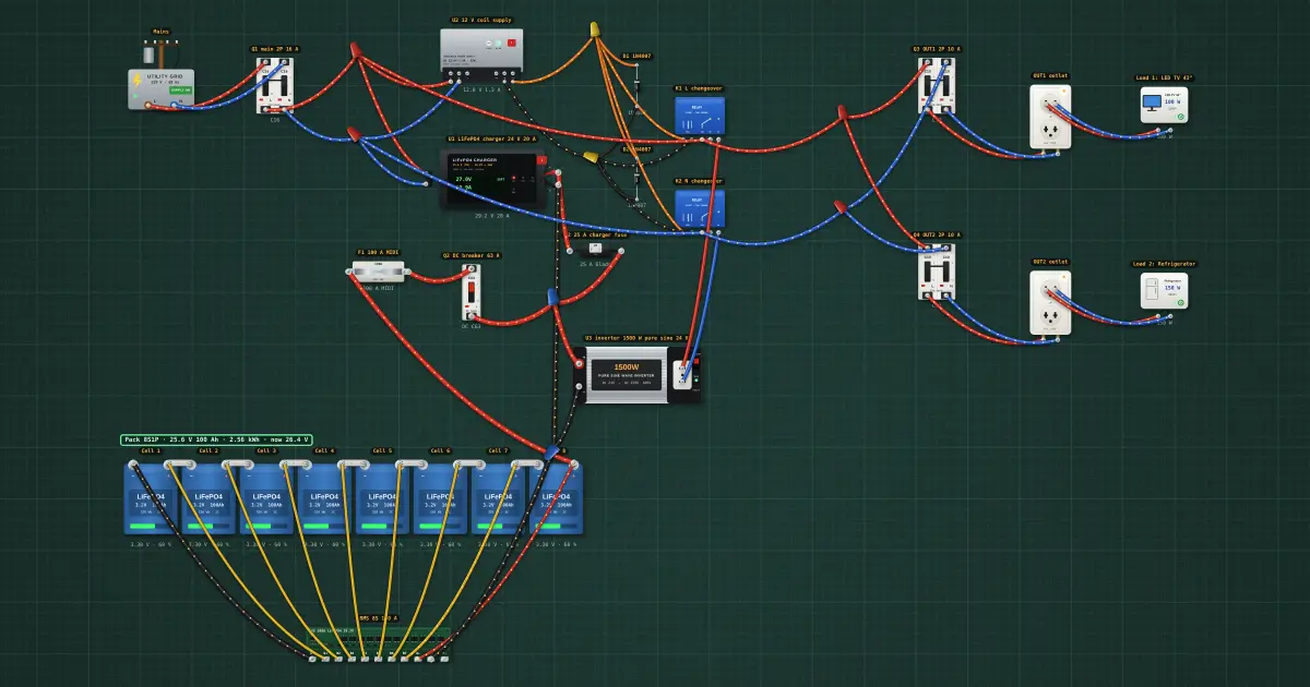
Home UPS on 8 × 3.2 V LiFePO4 cells + BMS: charger, inverter, changeover relays, two 220 V outputs
Keeps two 220 V circuits powered through outages from 8 × 3.2 V LiFePO4 cells; charges from the grid when it returns.
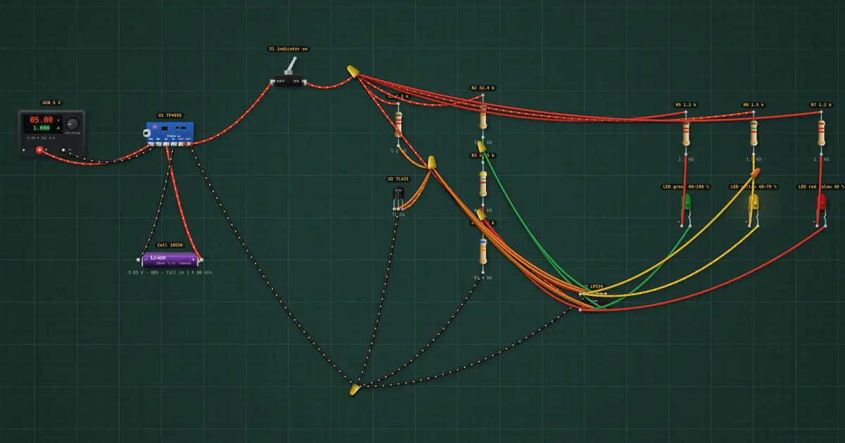
Single 18650 charger with a 3-LED charge indicator (green 80–100 %, yellow 40–79 %, red below 40 %)
Charges an 18650 from USB and shows its charge on three LEDs: green 80–100 %, yellow 40–79 %, red below 40 %.
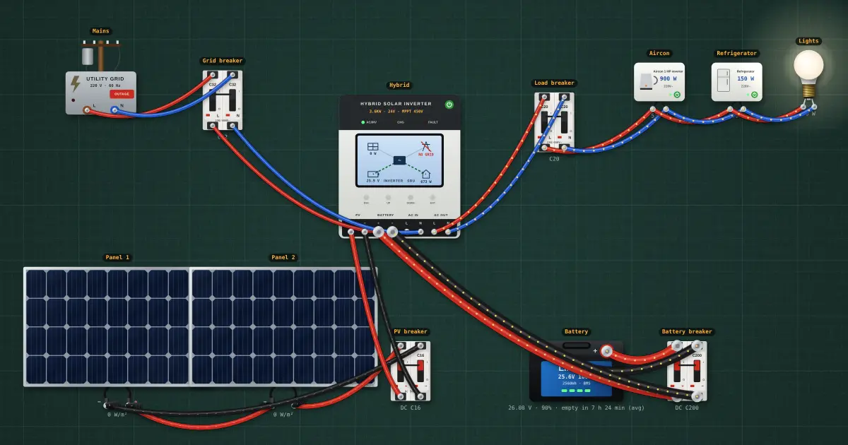
1 HP inverter aircon on a 3.6 kW hybrid at night: what the battery sees
Night-time: no sun, a 24 V 100 Ah LiFePO4 battery feeding a 3.6 kW hybrid, a 1 HP inverter aircon, a refrigerator and…
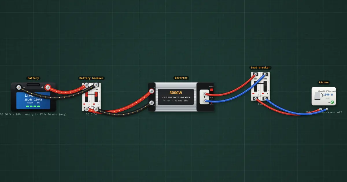
Why a 1.5 HP non-inverter aircon trips a 3 kW inverter at start-up
A 24 V LiFePO4 battery, a 3 kW pure-sine inverter and a 1.5 HP non-inverter aircon. Switch the aircon on and watch the…
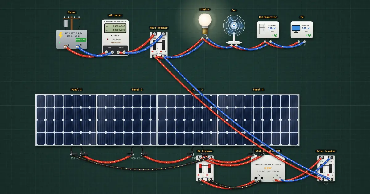
Grid-tie solar in a brownout: why the lights go out even at noon
The grid, a kWh meter and main breaker, a 3 kW grid-tie inverter on four panels, and the house loads. Switch the grid…
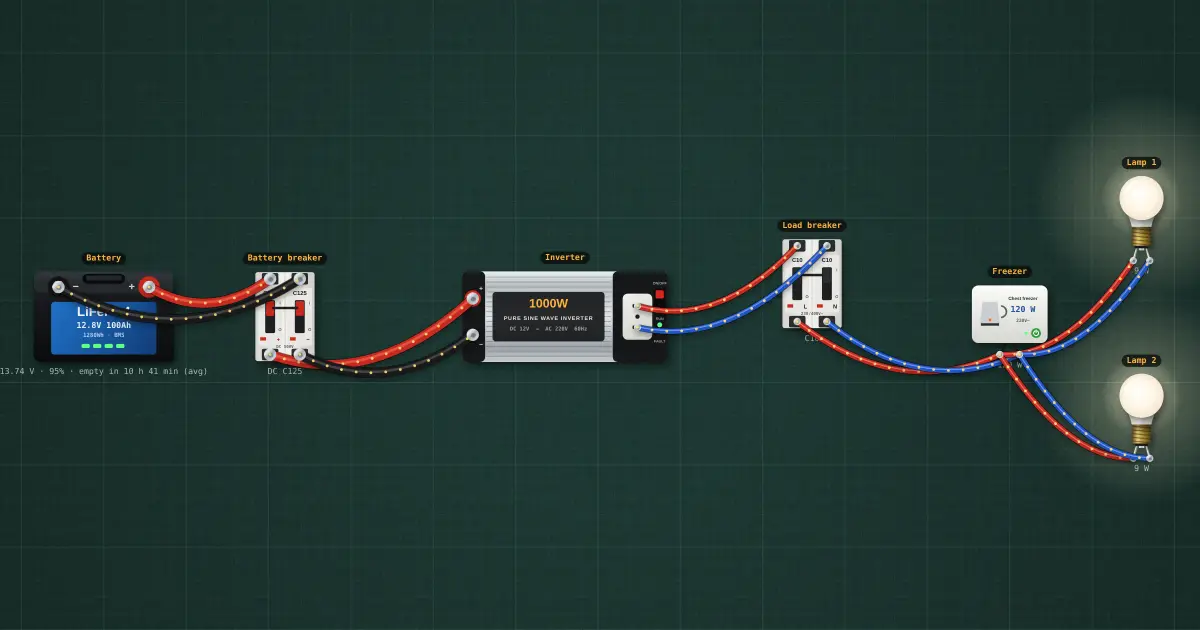
Sari-sari store freezer through a brownout: battery, inverter and hours
12 V 100 Ah LiFePO4 battery, 1000 W pure-sine inverter, a chest freezer and two LED bulbs. The panel shows the…
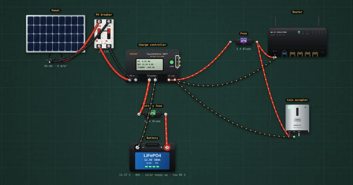
Piso Wi-Fi on solar: how big a panel and battery for a router and coin box
100 W panel, a 10 A MPPT charge controller, a 12 V 30 Ah LiFePO4 battery and the box: router plus coin acceptor on the…
USB and power interfaces
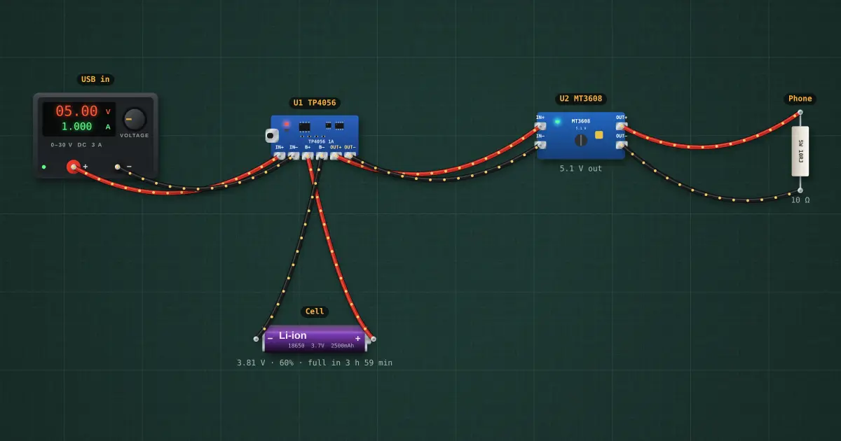
USB power bank
18650 charger plus protection plus a 5 V boost output.
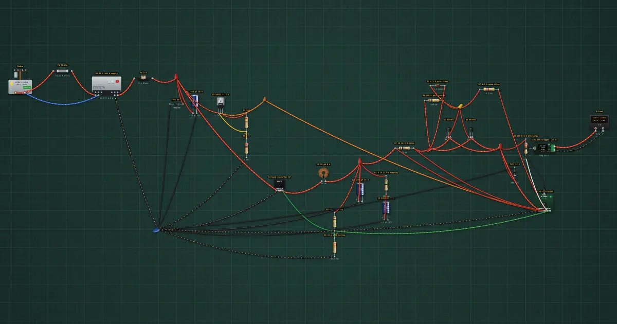
65 W USB-C PD stage on a ready-made 24 V supply: buck converter, PD controller, load switch
65 W USB-C PD charger: certified 24 V supply, buck converter, PD source controller, P-MOSFET load switch, with OCP…
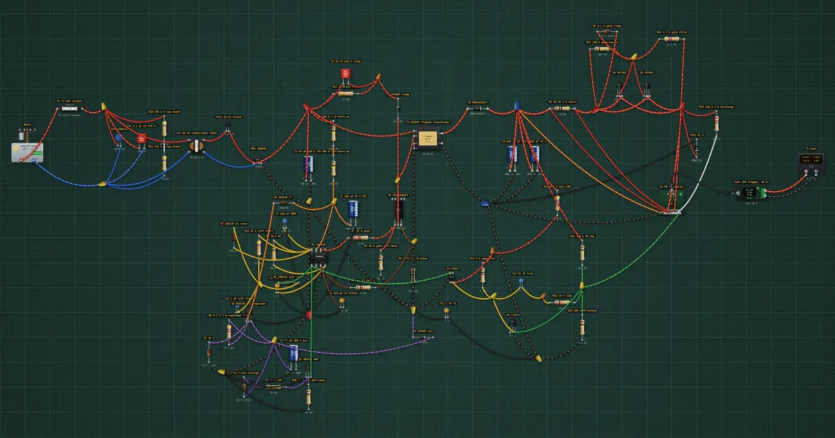
65 W USB-C PD charger from scratch: mains flyback (UC3844, 800 V MOSFET, PQ2625 transformer), TL431 + PC817 feedback, PD controller
65 W USB-C PD charger from parts: mains input filter, bridge and bulk, UC3844 flyback with RCD clamp and aux-powered…
Transistors and thyristors
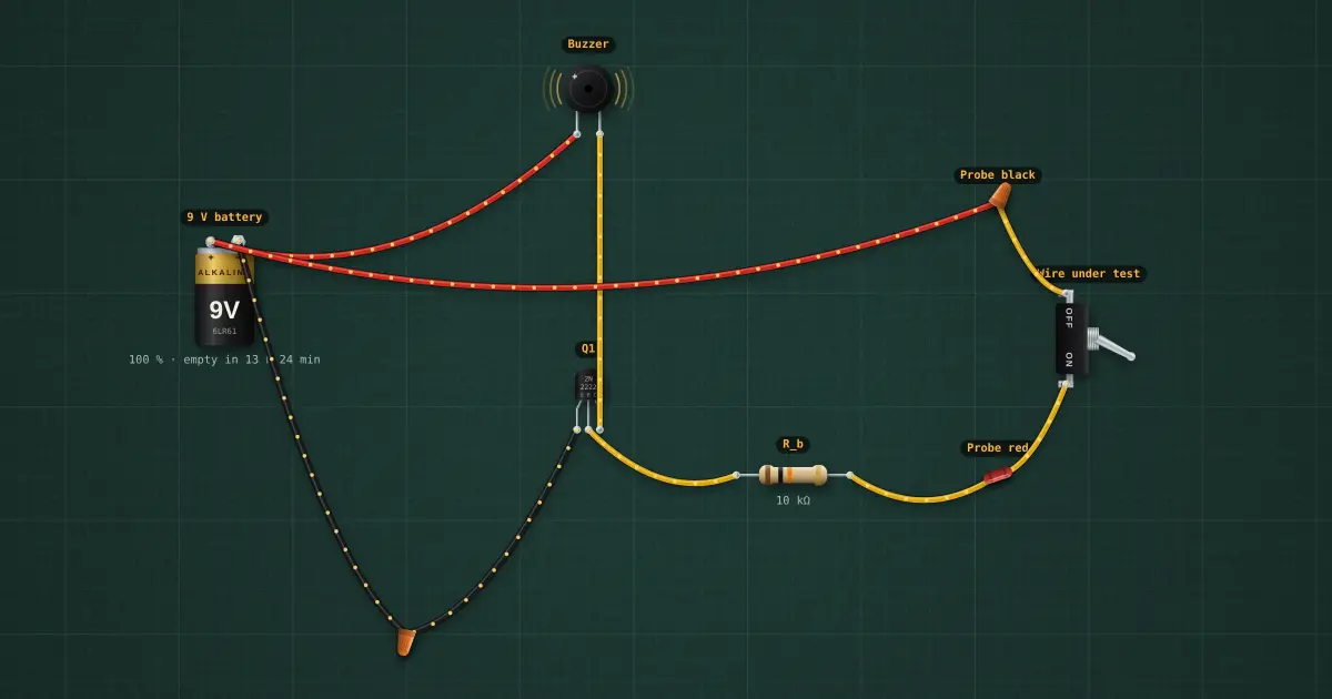
Continuity tester
Beeps on a closed circuit.
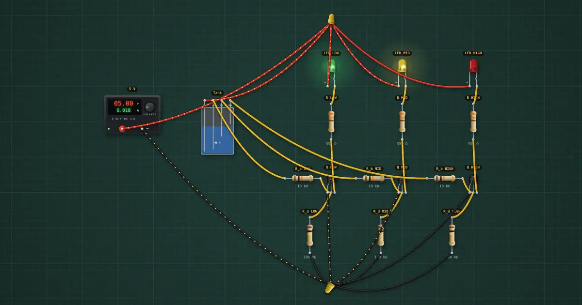
Water-level indicator
LEDs show tank level through probe wires.
Systems and capstones
Power, transformers and three-phase
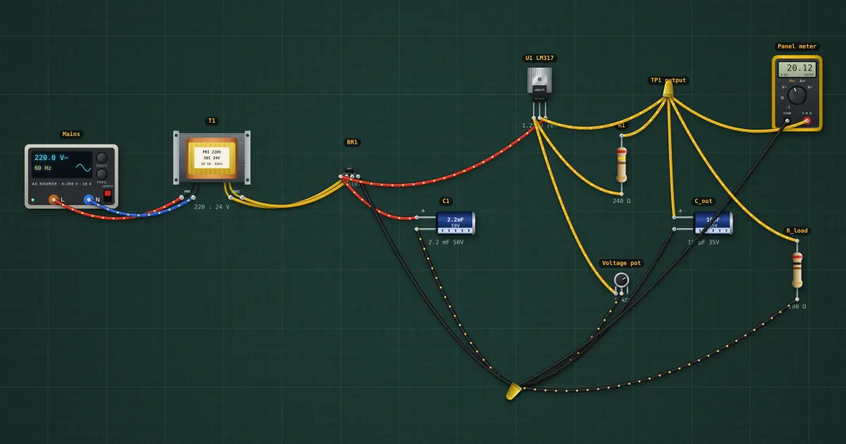
Adjustable bench supply 1.25–20 V
1.25–20 V with a panel meter.
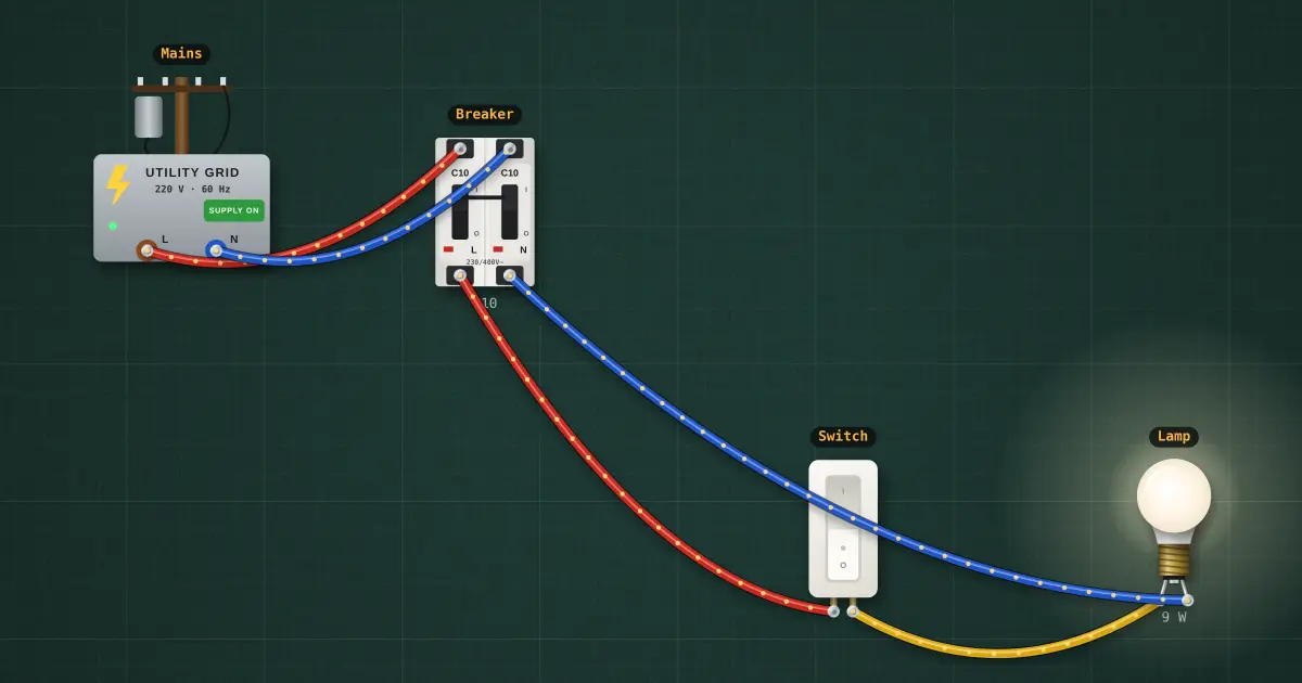
Light with one switch
One 9 W LED bulb on a 1-way wall switch, fed from a 10 A breaker.
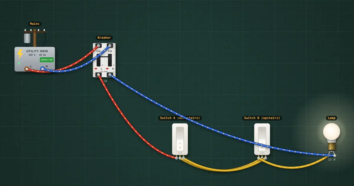
Staircase light: two 3-way switches
A 15 W lamp switched from two places with a pair of 3-way (2-way in British terms) switches.
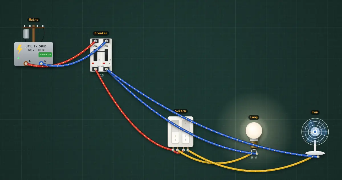
Fan and light on a 2-gang switch
A ceiling light (9 W) and a fan (40 W), each on its own rocker of one 2-gang switch.
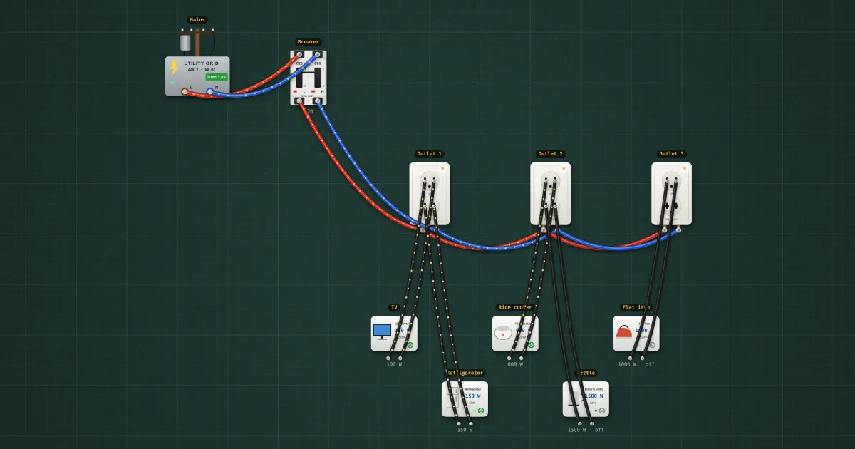
Outlet circuit: three outlets on a 20 A breaker
Three duplex outlets on 3.5 mm² wire and a 20 A breaker, with a TV, refrigerator, rice cooker, kettle and flat iron…
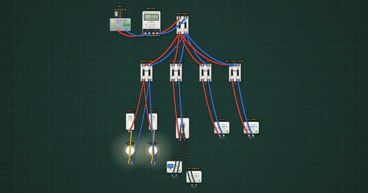
House panel: main breaker and four branch circuits
A 60 A main, four branch breakers, two switched lights, an outlet with a TV and refrigerator, a 1 HP aircon and a 3.5…
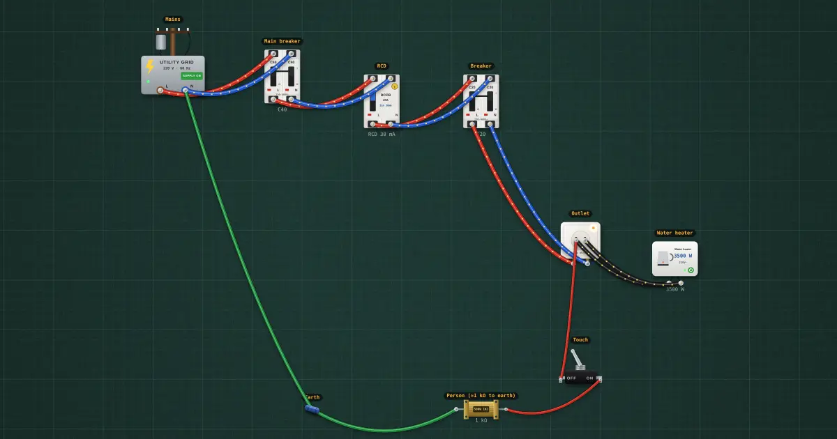
RCD protection: someone touches a live wire
A water-heater circuit behind a 30 mA RCD, with a switch that lets a "person" (about 1 kΩ, hand to wet feet) touch the…
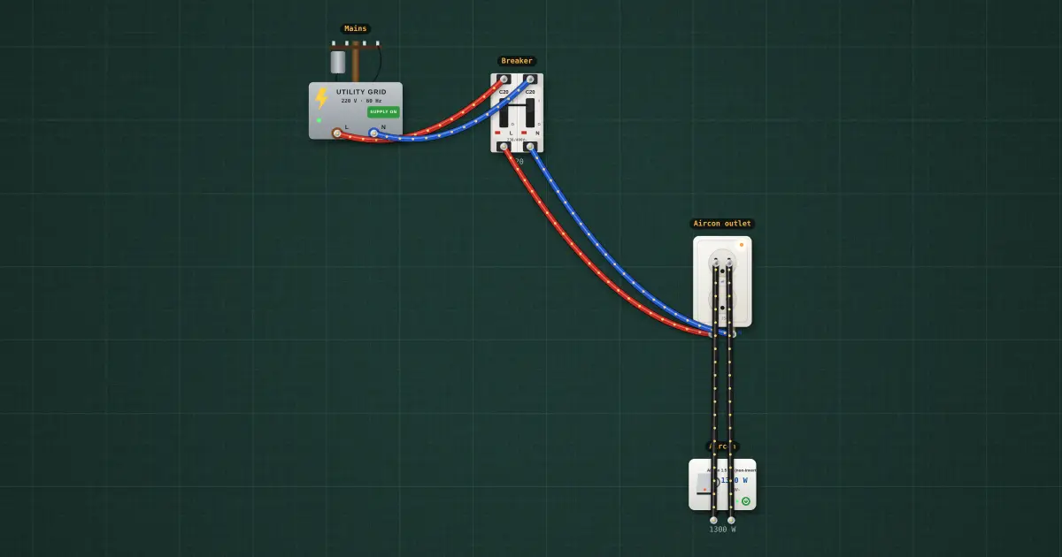
Aircon branch circuit: 1.5 HP on 3.5 mm² and a 20 A breaker, on its own
Mains through a 20 A breaker and 3.5 mm² wire to a 1.5 HP non-inverter aircon on its own outlet. The tests share the…
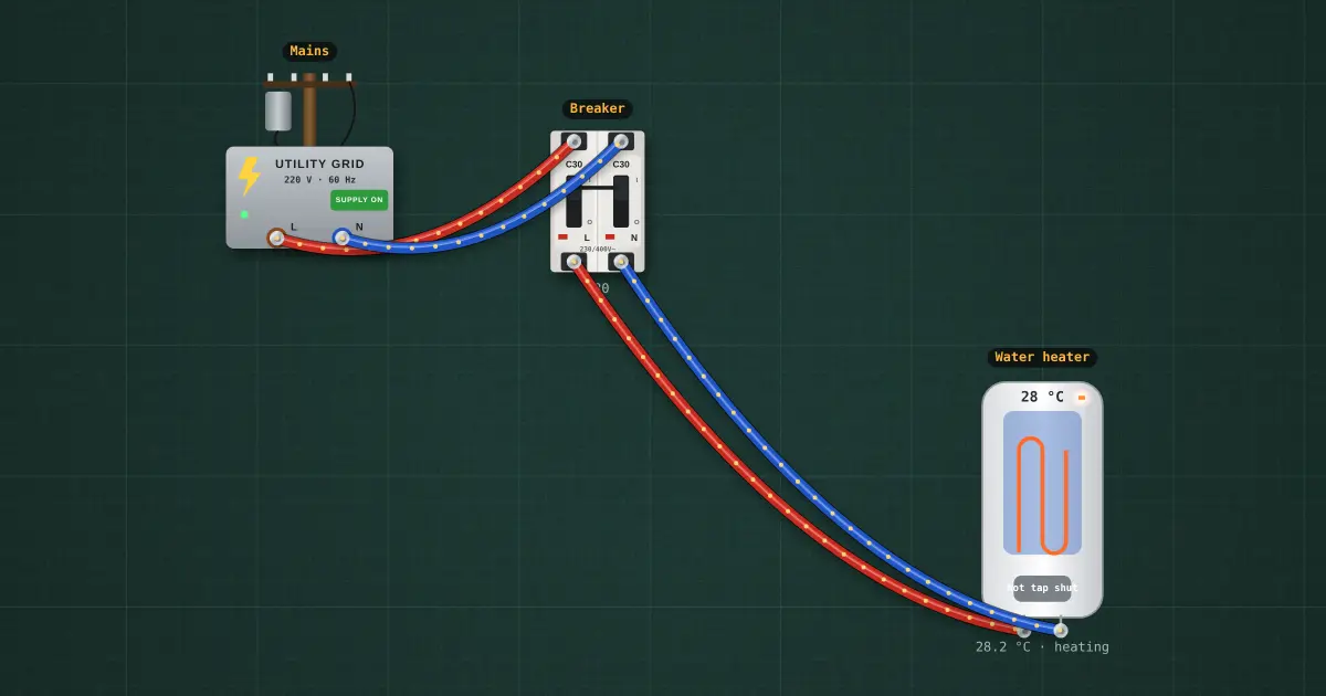
Water heater circuit: 3.5 kW on 5.5 mm² and a 30 A breaker
Mains through a 30 A breaker and 5.5 mm² wire to a 3.5 kW storage water heater. The tests raise it to 5 kW and try the…
Oscillators
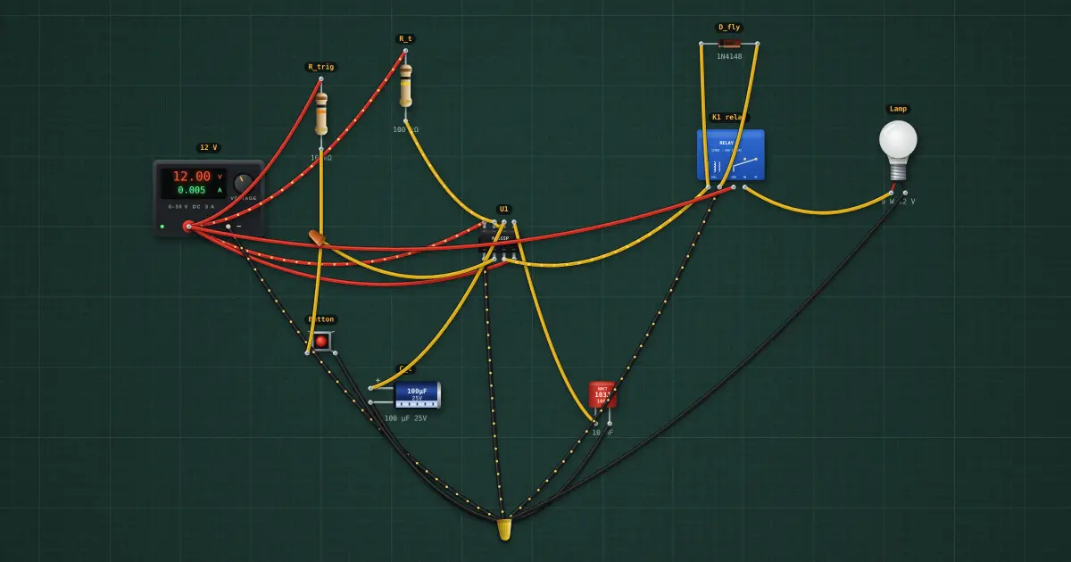
555 delay-off timer with relay
Switches a load off after a set time.
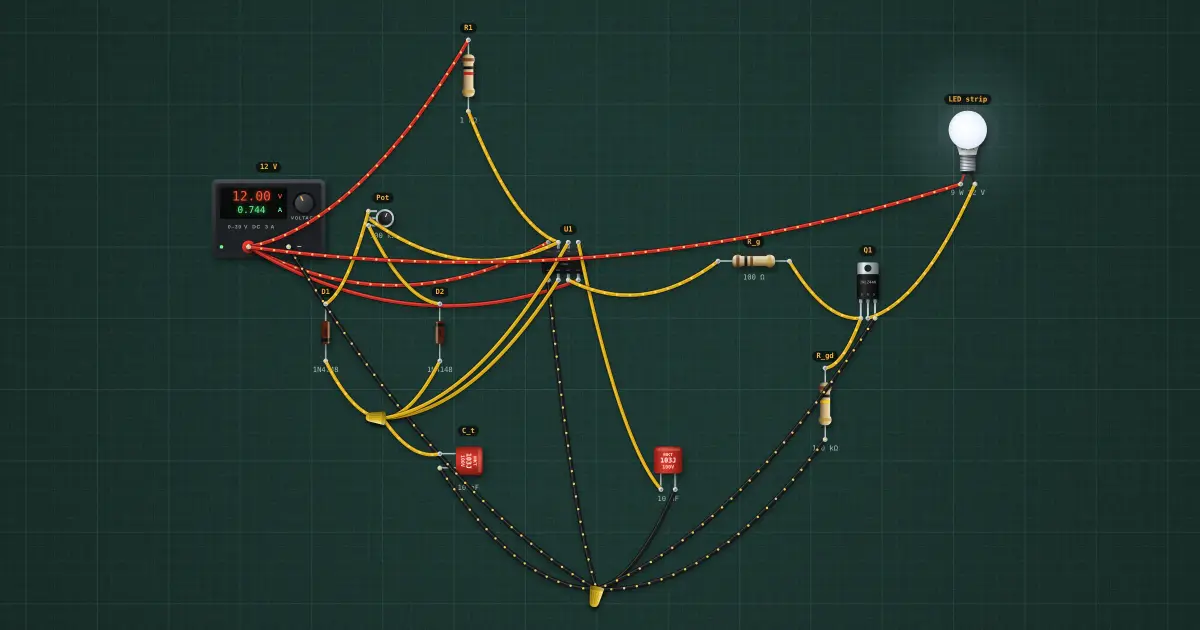
PWM fan or LED dimmer
Variable brightness or speed from a knob.
Embedded (ESP32)
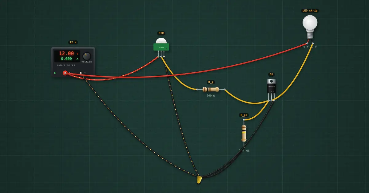
Motion-activated light
Lights for 30 s when someone passes.
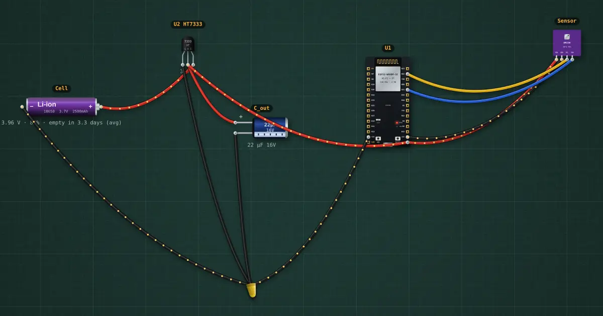
ESP32 battery sensor node
Wakes, reads a sensor, reports, sleeps.
Op-amps and analog ICs
Bench builds
Fundamentals
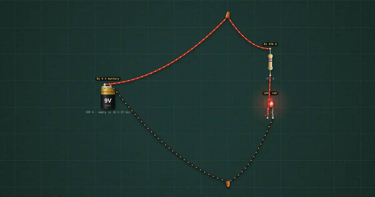
1. Resistor and LED: the first circuit
Step 1 of the automatic light: B1 (9 V) → R1 470 Ω → LED1 → back to B1. I = (9 − 2) / 470 ≈ 15 mA: bright, and well…
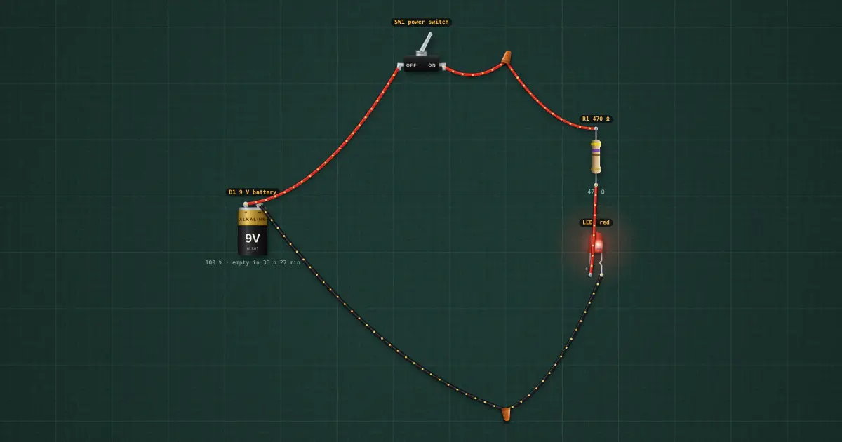
2. Adding a switch
Step 2 of the automatic light: SW1 goes between B1 + and R1. Off: the LED is dark and no current flows.
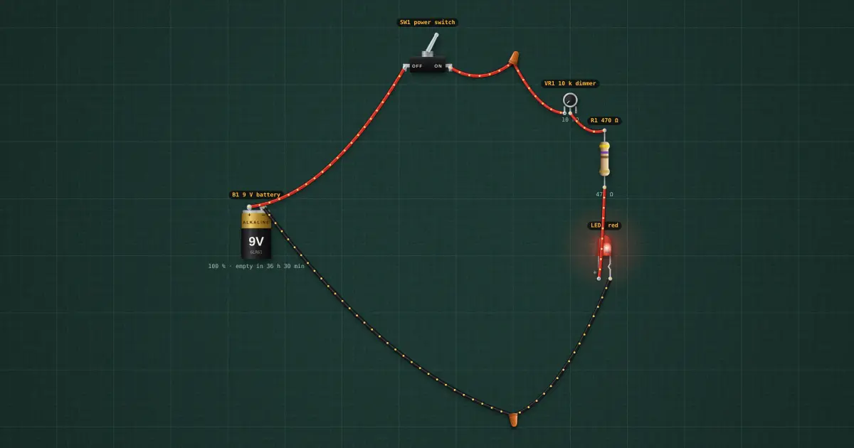
3. Potentiometer: a dimmer
Step 3 of the automatic light: VR1 (10 k) between the switch and R1. Knob at 0: about 15 mA. Knob at the far end…
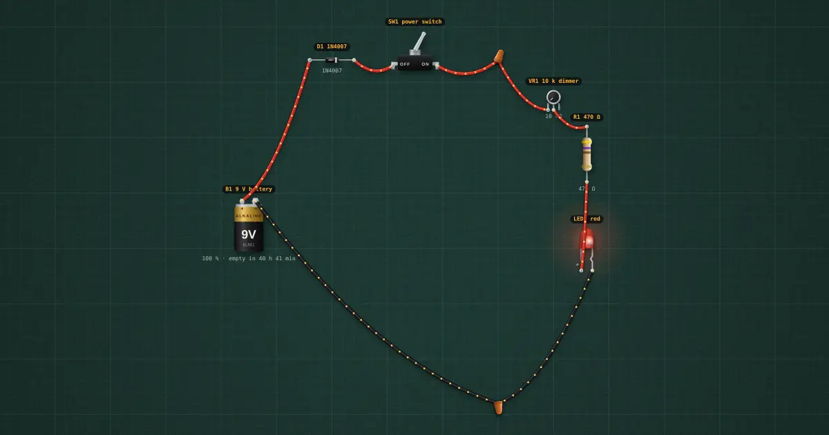
4. Diode: reverse-polarity protection
Step 4 of the automatic light: D1 in the + line right after the battery. The LED gets 0.7 V less (a little dimmer)…
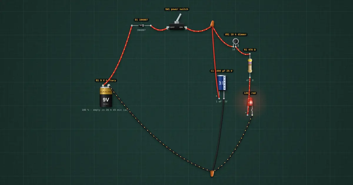
5. Capacitor: a soft fade-out
Step 5 of the automatic light: C1 1000 µF across the supply after the switch. Switch off and the LED fades over a…
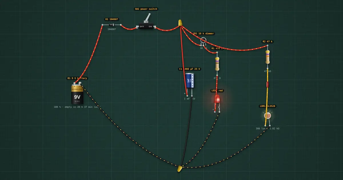
6. LDR: sensing light
Step 6 of the automatic light: R2 47 k from the supply to SENSE, LDR1 from SENSE to ground. Bright: the LDR is low…
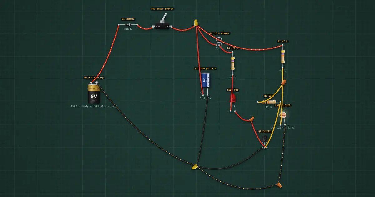
7. Transistor: the light switches itself
Step 7 of the automatic light: LED1 now goes to Q1’s collector instead of ground; SENSE drives the base through R3 10…
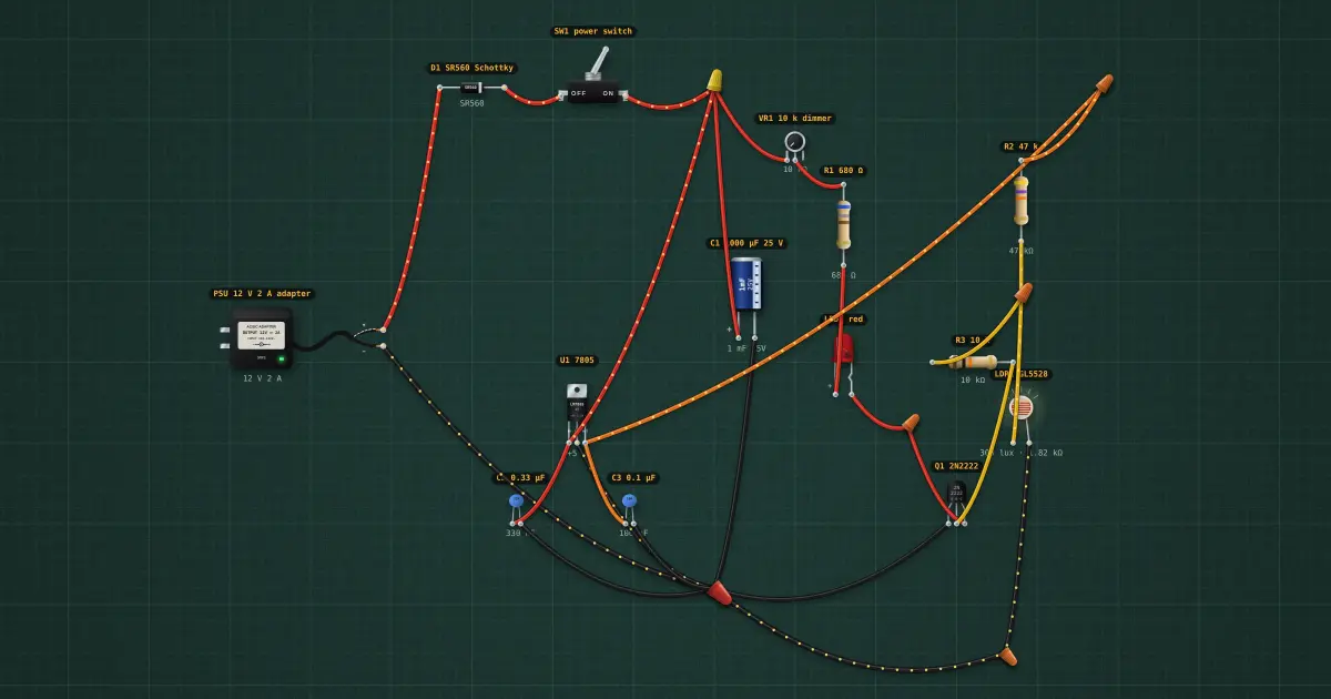
8. Voltage regulator: a 12 V supply and a steady 5 V
Step 8 of the automatic light: The build outgrows a 9 V battery, so it moves to a 12 V adapter (D1 still guards it)…
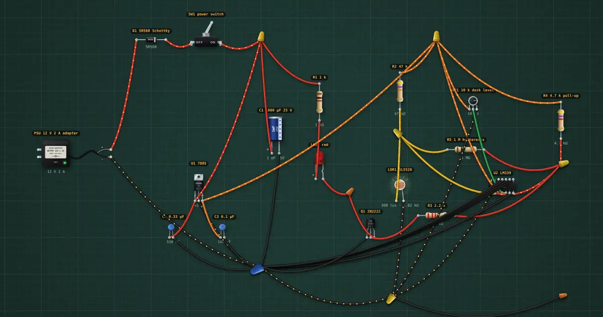
9. Comparator: a clean decision at dusk
Step 9 of the automatic light: VR1 gets a new job: it sets the dusk level on IN1− (the dimmer is gone; the LED becomes…
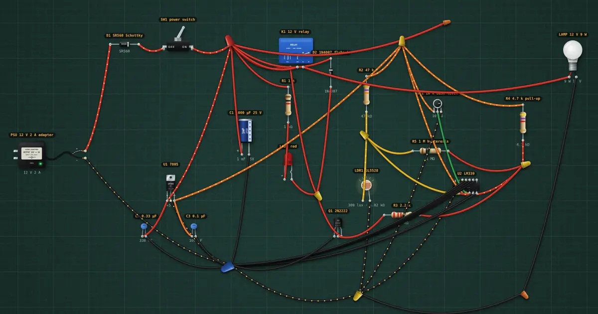
10. Relay: switching a real lamp
Step 10 of the automatic light: K1’s coil sits where the LED was, between + and Q1; D2 across it. Its contacts switch…
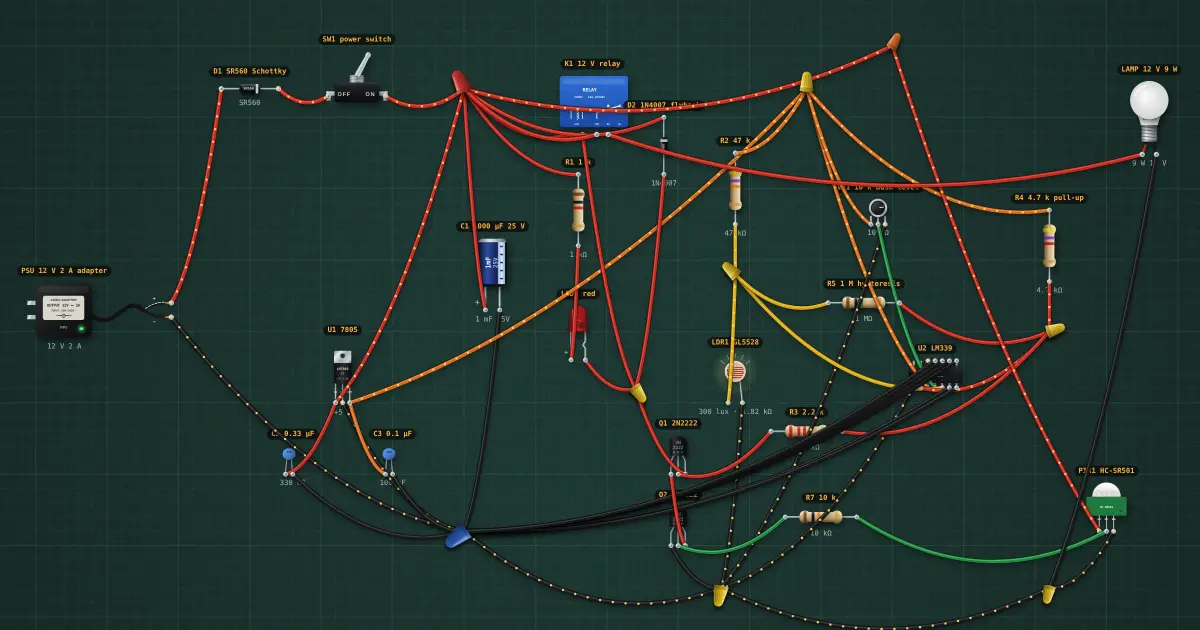
11. PIR sensor: only when someone is there
Step 11 of the automatic light: Q2 goes in series below Q1, its base driven by the PIR output. Now both must be on…
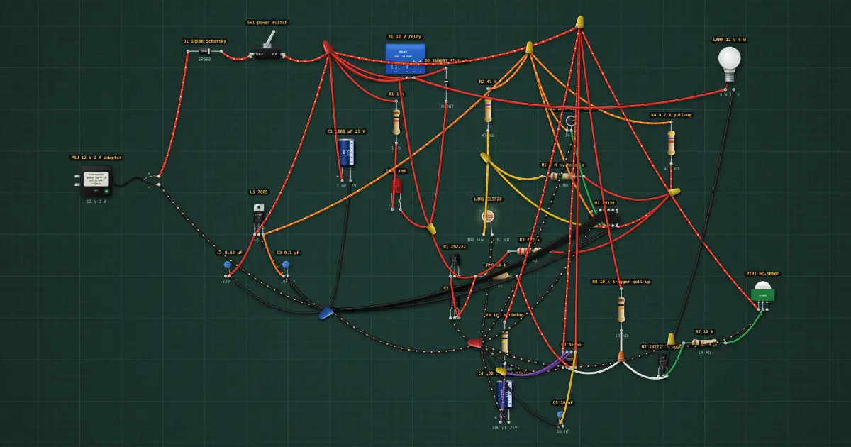
12. 555 timer: stay on after they pass
Step 12 of the automatic light: The PIR now drives Q2 as an inverter, pulling TRIG low while it sees movement (R8…
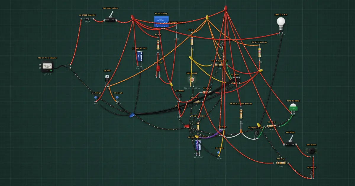
13. Buzzer: an alarm mode
Step 13 of the automatic light: Q4, driven from the same 555 output, switches BZ1 through SW2 (alarm on/off). With the…
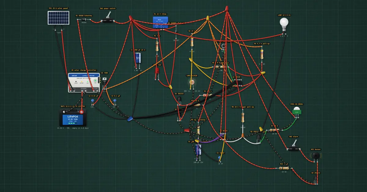
14. Solar: the light runs off-grid
Step 14 of the automatic light: The adapter is replaced by PV1 (20 W) → U5 charge controller → BAT1 12 Ah, and the…
Real Devices
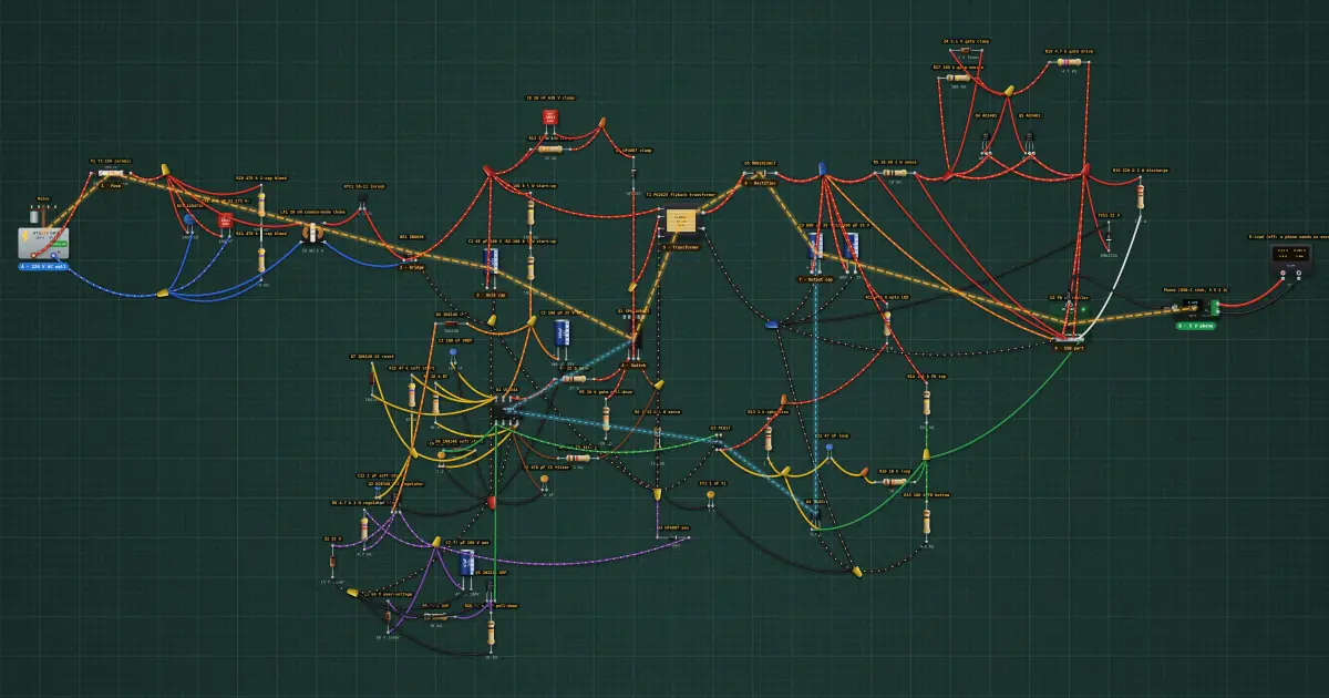
Real device: phone charger, 220 V AC wall to 5 V USB
A USB phone charger traced from the wall to the phone, every part annotated: fuse, bridge, bulk capacitor, switching…
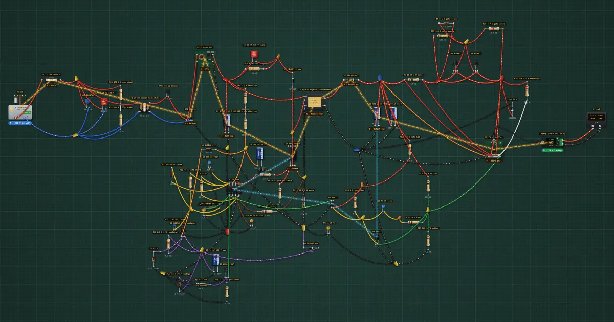
Real device: laptop charger, 220 V AC wall to 20 V with PFC
A 65 W laptop charger traced from the wall to the laptop: the phone charger's spine at higher power, with a boost…
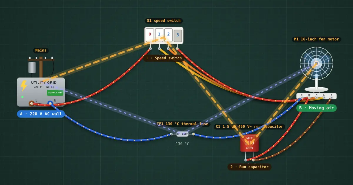
Real device: electric fan, 220 V AC to moving air
A 16-inch stand fan: a permanent-split-capacitor motor, its run capacitor, a piano-key speed switch on the winding…
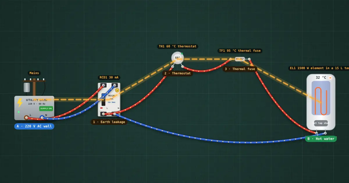
Real device: water heater, 220 V AC to hot water
A 15 L storage water heater: an RCD, a bimetal thermostat, a one-shot thermal fuse and a 1500 W sheathed element. The…