3. Potentiometer: a dimmer
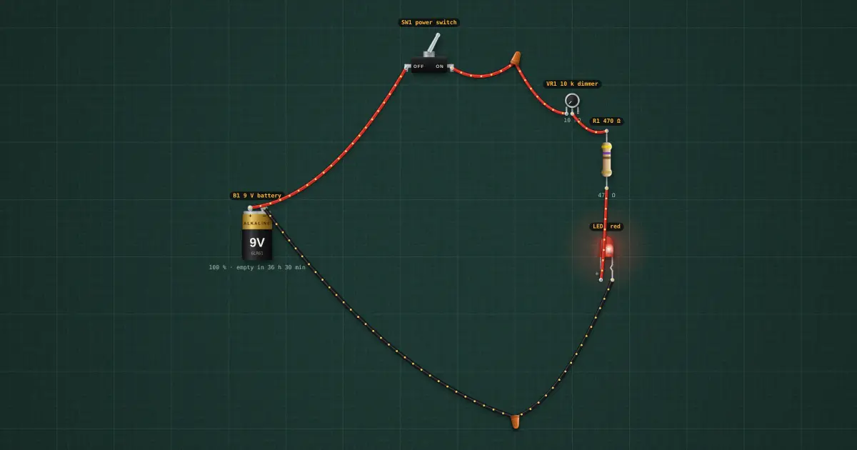
Step 3 of the automatic light: VR1 (10 k) between the switch and R1. Knob at 0: about 15 mA. Knob at the far end: 10.47 k in total, under 1 mA, a dim glow. Component 3 of 14: the potentiometer. A potentiometer is a resistor with a sliding contact (the wiper, the middle pin). Used with one end and the wiper it is a variable resistor (a rheostat); used with both ends it is an adjustable voltage divider. Here it is a rheostat in series with R1.
Build it in the labGuided build, test sheet and fault finding, free in your browser.
Parts list
Test procedure
Each test has an expected value and a pass range, like a factory test sheet:
- Dimmer at minimum resistance
- Dimmer at maximum
How it works
The potentiometer. A potentiometer is a resistor with a sliding contact (the wiper, the middle pin). Used with one end and the wiper it is a variable resistor (a rheostat); used with both ends it is an adjustable voltage divider. Here it is a rheostat in series with R1.
Reading it. Printed code: B10K = 10 kΩ linear (A = logarithmic, for audio volume). The value is the resistance end to end. R1 stays in series so that at zero ohms the LED is still protected.
Testing it. Ω between the two outer pins: the full value, whatever the knob. Outer pin to wiper: smoothly from 0 to the full value as you turn it; any jump or open spot is a worn track.
In the build. VR1 (10 k) between the switch and R1. Knob at 0: about 15 mA. Knob at the far end: 10.47 k in total, under 1 mA, a dim glow.
Builds on lesson 2: everything from before is still there.
Next: lesson 4, diode.
Things to try
- Drag the VR1 slider and watch the brightness and the current.
- At the far end the LED is still faintly lit: that is the 0.7 mA through 10.47 k.
Background
One circuit, built up one part at a time: by lesson 14 it is a solar-powered, dusk-sensing, motion-triggered timed lamp with an alarm.