1. Resistor and LED: the first circuit
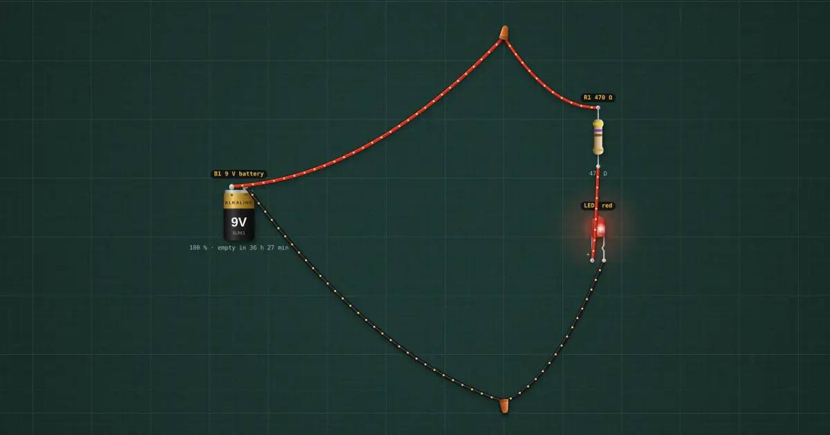
Step 1 of the automatic light: B1 (9 V) → R1 470 Ω → LED1 → back to B1. I = (9 − 2) / 470 ≈ 15 mA: bright, and well inside the LED’s 20 mA. Component 1 of 14: the resistor. A resistor turns a voltage into a definite current: I = V / R. It is the most common part on any board, and its job here is the one you will meet again and again: limiting the current through an LED.
Build it in the labGuided build, test sheet and fault finding, free in your browser.
Parts list
Test procedure
Each test has an expected value and a pass range, like a factory test sheet:
- LED current
- Voltage across R1
How it works
The resistor. A resistor turns a voltage into a definite current: I = V / R. It is the most common part on any board, and its job here is the one you will meet again and again: limiting the current through an LED.
Reading it. Value by colour bands (yellow-violet-brown = 470 Ω), tolerance band (gold 5 %, brown 1 %), power by size (a small ¼ W body is the usual). The LED: the long leg is the anode (+), the flat side of the rim is the cathode (−); red needs about 2 V, white/blue about 3 V.
Testing it. Out of circuit, the meter on Ω reads the value within tolerance. In circuit, measure the voltage across it and divide by R: that is the current. An LED tests with the meter’s diode range: it glows faintly and reads 1.6–3 V one way, nothing the other.
In the build. B1 (9 V) → R1 470 Ω → LED1 → back to B1. I = (9 − 2) / 470 ≈ 15 mA: bright, and well inside the LED’s 20 mA.
Next: lesson 2, switch.
Things to try
- Change R1 to 1 k: dimmer, about 7 mA.
- Change R1 to 47 Ω and watch the LED burn out (Undo restores it). That is why the resistor is there.
Background
One circuit, built up one part at a time: by lesson 14 it is a solar-powered, dusk-sensing, motion-triggered timed lamp with an alarm.