9. Comparator: a clean decision at dusk
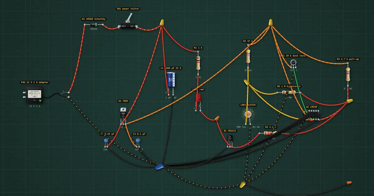
Step 9 of the automatic light: VR1 gets a new job: it sets the dusk level on IN1− (the dimmer is gone; the LED becomes the “lamp on” indicator with R1 1 k). SENSE goes to IN1+. R4 pulls the output up to 5 V, R3 2.2 k drives Q1 hard, and R5 1 M from the output back to SENSE adds hysteresis: once on, it needs a bit more light to turn off. Component 9 of 14: the comparator (lm339). A comparator compares two voltages and gives a hard yes/no: output high when IN+ is above IN−, low when it is below. No in-between, so the transistor after it is either fully on or fully off. A little positive feedback (hysteresis) stops it chattering when the light hovers right at the threshold.
Build it in the labGuided build, test sheet and fault finding, free in your browser.
Parts list
- DC adapter
- Schottky diode
- Toggle switch
- Electrolytic capacitor
- 5 × Resistor
- LED
- 7805 regulator
- 2 × Ceramic capacitor
- Photoresistor (LDR)
- NPN transistor
- LM339 quad comparator
- Potentiometer
Test procedure
Each test has an expected value and a pass range, like a factory test sheet:
- Dark: Q1 fully on
- Daylight: indicator off
- Dark: indicator on
How it works
The comparator (lm339). A comparator compares two voltages and gives a hard yes/no: output high when IN+ is above IN−, low when it is below. No in-between, so the transistor after it is either fully on or fully off. A little positive feedback (hysteresis) stops it chattering when the light hovers right at the threshold.
Reading it. LM339: four comparators in one DIP-14, open-collector outputs (each needs a pull-up resistor to the supply). Unused inputs go to ground. LM393 is the same with two.
Testing it. Powered: set IN+ above IN− with a pot and the output (with its pull-up) reads the supply; below, it reads near 0 V. A floating output with no pull-up reads nothing useful: that is normal for open collector.
In the build. VR1 gets a new job: it sets the dusk level on IN1− (the dimmer is gone; the LED becomes the “lamp on” indicator with R1 1 k). SENSE goes to IN1+. R4 pulls the output up to 5 V, R3 2.2 k drives Q1 hard, and R5 1 M from the output back to SENSE adds hysteresis: once on, it needs a bit more light to turn off.
Builds on lesson 8: everything from before is still there.
Next: lesson 10, relay (and a flyback diode).
Things to try
- Slide the LDR light level slowly through dusk: the LED snaps on and off instead of fading.
- Turn VR1 to move the dusk level.
- Delete R5 and sweep again near the threshold: with no hysteresis it switches at exactly the same point both ways.
Background
One circuit, built up one part at a time: by lesson 14 it is a solar-powered, dusk-sensing, motion-triggered timed lamp with an alarm.