Real device: laptop charger, 220 V AC wall to 20 V with PFC
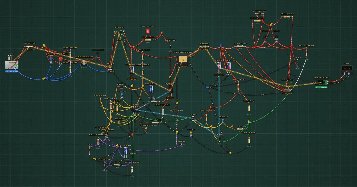
A 65 W laptop charger traced from the wall to the laptop: the phone charger's spine at higher power, with a boost power-factor corrector in front of the bulk capacitor.
Build it in the labGuided build, test sheet and fault finding, free in your browser.
Parts list
- Utility grid
- Fuse
- MOV varistor
- 2 × Film capacitor
- 23 × Resistor
- Common-mode choke
- NTC thermistor
- Bridge rectifier
- 5 × Electrolytic capacitor
- Flyback transformer
- 2 × Rectifier diode
- High-voltage N-MOSFET
- Current-mode PWM controller
- 6 × Ceramic capacitor
- 3 × Signal diode
- NPN transistor, 300 V
- 3 × Zener diode
- NPN transistor
- Schottky diode
- Optocoupler
- TL431 reference
- 2 × P-channel MOSFET
- TVS diode
- USB-C PD source controller
- USB-C PD trigger + meter
- Electronic load
- Boost PFC stage
Test procedure
Each test has an expected value and a pass range, like a factory test sheet:
- PFC holds the bus at 390 V
- 20 V, 65 W at the laptop
- Power factor with the PFC on
- Power factor with the PFC off
- Q1 drain peak on the 390 V bus
How it works
A laptop brick is the phone charger scaled up, with one block added: power-factor correction. Without it, the bridge only conducts in short, tall spikes at the top of each mains cycle, which heats house wiring and distorts the mains for everyone. The PFC stage makes the charger draw a smooth sine wave instead. (USB-C bricks run at 20 V; older barrel bricks at 19–19.5 V. Same machine.)
A220 V AC at the wall plug.B20 V at 3.25 A (65 W) into the laptop, isolated from the mains, drawn from the wall at a power factor near 1.
The path, A to B
- 220 V AC wall (Mains). Point A: the wall, 220 V at 60 Hz, which peaks at 311 V. Everything on the left of the transformer and the optocoupler is at this potential.
- Fuse (F1). Fault safety. A slow-blow 3.15 A fuse that ignores the switch-on surge but opens if anything behind it shorts, so a failed part becomes a dead charger instead of a fire. Ceramic and sand-filled, because a short right behind the bridge can draw far more current than a glass tube can safely break.
- Bridge (BR1). AC to pulsing DC. Four diodes flip the negative half of every cycle up, giving 120 bumps a second that all point the same way.
- PFC (PFC1). Power-factor correction. A boost converter between the bridge and C1 that draws current in proportion to the instantaneous mains voltage, so the wall sees a resistor, not a spike-drawing rectifier. It also lifts the bus to a steady 390 V. Its controller turns off in the inspector to compare: watch the mains current and power factor change.
- Bulk cap (C1). Bulk store, now behind the PFC. It sits at a regulated 390 V whatever the mains does, so it is a 450 V part: a 400 V capacitor at 390 V would have no margin left.
- Switch (Q1). The switch. An 800 V MOSFET chops the bulk voltage into the transformer about 70,000 times a second. Switching that fast is what lets a transformer the size of a sugar cube do the work of a 60 Hz one ten times its weight.
- Transformer (T1). Step-down and isolation in one. The flyback transformer stores energy in its core while Q1 is on and hands it to the secondary when Q1 turns off. The 40 : 8 turns ratio brings ~300 V down to the output, and the insulation between the windings is what keeps the mains away from you.
- Rectifier (D5). Output rectifier. A dual Schottky: its low forward drop means less heat at several amps.
- Output cap (C9). Clean output. With C10, 1360 µF of low-ESR capacitance soaks up the transformer's pulses and leaves steady DC. Two in parallel share the ripple current, which is what wears electrolytics out.
- USB-C port (U2). The PD controller. It talks to the device over the cable's CC wire, agrees a voltage, then moves the output there by pulling on the TL431's divider.
- 20 V laptop (Laptop). Point B: the laptop. It asks for 20 V over USB-C PD; the PD controller raises the output from 5 V to 20 V by pulling on the TL431's divider. The trigger draws 1.5 A of the 3.25 A; the E-load stands in for the rest.
The loop back: C9 → U4 → U3 → U1 → Q1, exactly as in the phone charger. The PFC has its own, much slower loop: it watches the 390 V bus and adjusts how much current it draws per volt of mains, slowly enough (a few hertz) that the current keeps the mains' sine shape.
Every other part, and why
- RV1: Surge clamp. A varistor that conducts hard above about 470 V peak, soaking up lightning and switching spikes on the line before they reach the bridge and the MOSFET.
- CX1: Noise filter. An X2 safety capacitor across the line shorts the charger's own high-frequency noise back on itself so it doesn't travel down the house wiring. X2-rated means it is built to fail open, never short.
- R20: Safety bleed. With R21 it drains CX1 after you pull the plug, so the pins can't bite you. Two in series because one small resistor isn't rated for the whole mains voltage.
- R21: Safety bleed, the second half of R20 (see R20).
- LF1: Noise filter. A common-mode choke: line and neutral are wound on one core, so the normal 60 Hz current cancels in it, while noise that leaves on both wires together sees a high impedance.
- NTC1: Inrush limiter. Cold, it is about 5 Ω, which tames the surge into the empty C1 at switch-on. Current warms it and it drops to a fraction of an ohm, so it costs almost nothing while running.
- U1: The primary-side brain. The UC3844 runs the oscillator, drives Q1's gate, and ends each pulse when the current in R6 reaches the level the feedback asks for.
- R6: Current sense. The voltage across 0.33 Ω tells U1 the transformer current on every cycle; at 1 V (3 A) U1 cuts the pulse short. That is the built-in short-circuit limit, acting within microseconds.
- D2: Clamp. Each time Q1 turns off, the transformer's leakage inductance kicks a spike. D2 dumps it into C8, and R11 burns it off as heat, so the drain stays well under 800 V.
- C8: Clamp capacitor: catches the leakage spike (see D2).
- R11: Clamp resistor: turns the caught spike into heat (see D2). 3 W because it does this 70,000 times a second.
- R1: Start-up. Before the transformer runs there is no aux power, so R1 and R2 trickle current from the bulk into C2 until U1 has enough voltage to start.
- R2: Start-up, with R1. Two in series to share the voltage.
- C2: VCC store. Holds U1's supply up during start-up and between aux pulses.
- C3: Decoupling for U1's 5 V reference, so the timing and the current limit stay clean.
- R3: Timing, with C4: sets U1's oscillator at about 143 kHz, 72 kHz at the gate.
- C4: Timing capacitor (see R3).
- R22: Soft start, with C12: lets the output come up over tens of milliseconds instead of slamming the transformer at full power.
- C12: Soft-start capacitor (see R22).
- D6: Soft-start diode: holds COMP down while C12 charges.
- D7: Resets the soft start when the controller stops, so every restart is soft too.
- R4: Gate resistor: slows Q1's edges slightly, cutting ringing and radio noise.
- R5: Gate pull-down: keeps Q1 firmly off whenever U1 isn't driving it, so it can never sit half-on and cook.
- R7: Current-sense filter, with C6: hides the spike at the start of each pulse so U1 doesn't mistake it for an overcurrent.
- C6: Current-sense filter capacitor (see R7).
- D3: Aux supply. A small extra winding on T1 powers U1 once switching starts, so the start-up resistors only work for a second.
- C7: Aux reservoir for the winding's pulses.
- Q2: VCC regulator. The aux voltage rises with the output (5 V → 20 V); Q2 with R8 and Z2 holds U1's VCC near 14 V either way.
- R8: Bias for the VCC regulator (see Q2).
- Z2: 15 V reference for the VCC regulator (see Q2).
- D4: Steers the regulated aux into VCC.
- Z3: Over-voltage watch, the second way to stop. If the feedback fails and the output soars, the aux rises with it; Z3 conducts, Q3 pulls COMP down and U1 stops switching.
- R9: Over-voltage network (see Z3).
- R10: Over-voltage network (see Z3).
- Q3: Over-voltage switch (see Z3).
- C10: Output capacitor, sharing the ripple with C9.
- CY1: Y capacitor. Gives high-frequency noise a short way back to the primary instead of out along your cable. Y-rated, so it fails open: it bridges the isolation barrier.
- U3: Regulation across the barrier. The opto's LED on the output side tells the primary how hard to work, with light, so no wire crosses the isolation gap.
- R12: Feeds the opto LED from the output.
- R13: Keeps the TL431 biased even when the opto LED is nearly off.
- U4: The reference. The TL431 compares the output (through R14 and R15) with its own precise 2.5 V and pulls more current through the opto LED as the output rises.
- R14: Output divider top: with R15, 2.5 V at the TL431 means 5.0 V out.
- R15: Output divider bottom (see R14).
- C11: Loop compensation, with R16: sets how fast the loop reacts so it settles instead of oscillating.
- R16: Loop compensation (see C11).
- RS: USB current sense: the PD controller reads it to hold the current it agreed with the device.
- Q4: Load switch, with Q5. Back-to-back P-MOSFETs keep the port dead until a device asks for power, and stop current flowing back in.
- Q5: Load switch, the second half of the back-to-back pair (see Q4).
- R17: Gate pull-up: holds the load switch off by default.
- Z4: Gate clamp: keeps the load switch's gate under its 12 V limit at 20 V out.
- R18: Gate drive from the PD controller.
- TVS1: Clamps spikes on the port, from hot-plugging or a static zap.
- R19: Discharge: pulls the port down fast when the voltage steps down or the cable is unplugged.
- E-load: Stands in for the laptop's own battery charger, drawing the other 1.75 A.
Why it lasts
- Everything that made the phone charger last, at 65 W: isolation through the transformer, the opto and a Y capacitor; current limit, opto loop, over-voltage watch and fuse as four separate ways to stop.
- A kinder load on the mains. With the PFC on, the mains current is a sine in step with the voltage (power factor about 0.98), so its rms is the least it can be for the power: the fuse, the bridge, the plug and your house wiring carry less current for the same watts. Turn the PFC off and the same 65 W takes about 1.7 times the rms current (power factor near 0.6).
- A steady bus. Because the PFC holds C1 at 390 V from any mains between 90 and 264 V, the flyback always works at the same point: one design for every country.
- Margins kept: C1 rated 450 V for a 390 V bus; Q1 peaks near 600 V of 800 V; the PFC stops if the bus ever goes 25 V over its target.
- Under 75 W the rules don't demand PFC (IEC 61000-3-2), which is why many 65 W bricks skip it; from about 75 W up every one has it. This one has it so you can see what it does.
On the mat: the amber line is the energy path from A to B, the dashed blue line the feedback loop. Click any part: why it is there shows at the top of the inspector. Turn the path off or on in the View menu (Real-device path & notes); the Thermal view shows where the heat goes.
Background
Active PFC spread through the 1990s and 2000s as standards (IEC 61000-3-2, then 80 PLUS for PCs) limited the harmonic current a mains appliance may draw. The boost topology with an average-current controller (UC3854, 1989) is still the classic.