Real device: electric fan, 220 V AC to moving air
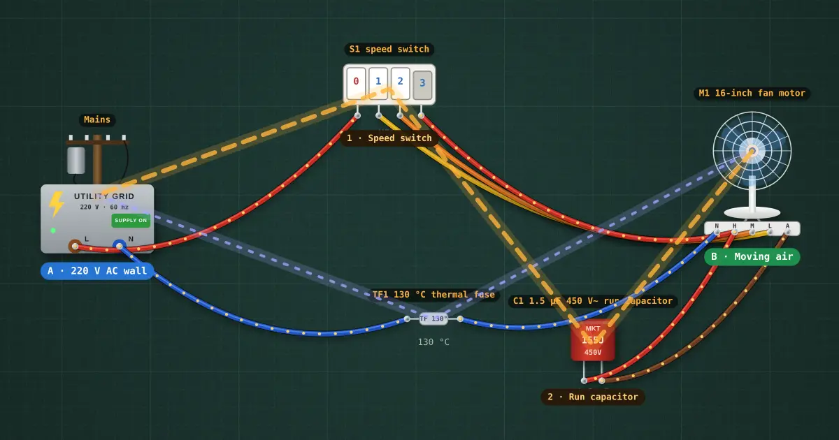
A 16-inch stand fan: a permanent-split-capacitor motor, its run capacitor, a piano-key speed switch on the winding taps and the thermal fuse buried in the winding.
Build it in the labGuided build, test sheet and fault finding, free in your browser.
Parts list
Test procedure
Each test has an expected value and a pass range, like a factory test sheet:
- High speed
- Power on high
- Low is slower than high
- The capacitor makes the phase shift
- No capacitor: it hums and does not start
- Stalled, the thermal fuse opens before the winding cooks
How it works
A stand fan has almost nothing in it, which is why one lasts twenty years. The interesting part is the capacitor: a single-phase supply can only make a magnetic field that pulses back and forth, and a pulsing field can't choose a direction to turn. The run capacitor shifts the current in a second winding by nearly 90°, and two windings 90° apart, fed 90° apart, make a field that rotates.
A220 V AC at the wall plug.BMoving air: about 1350 rpm and 55 m³ a minute on high.
The path, A to B
- 220 V AC wall (Mains). Point A: the wall, 220 V at 60 Hz.
- Speed switch (S1). Speed taps. Each key sends the line to a different tap: 3 goes straight to the main winding, 2 and 1 go through extra turns first. Those turns drop part of the voltage, the motor makes less torque and settles at a lower speed. No electronics: nothing to fail but a contact.
- Run capacitor (C1). The phase shift. 1.5 µF in series with the auxiliary winding makes its current lead the main winding's by about 80–90°. Two windings set 90° apart around the stator, carrying currents 90° apart in time, add up to a field that rotates, and the rotor is dragged round after it. It sees about as much voltage as the mains itself (220 V rms, 310 V peaks), so it is a 450 V~ part: that margin is what lets it last years.
- Moving air (M1). Point B: the motor and blades. A squirrel-cage rotor (no brushes, nothing touching but the bearings) chases the rotating field, always slipping a little behind the 1800 rpm field, which is what makes it pull. The rotor's pull is the power that becomes air.
The loop back: The return: every winding comes back through the common wire, N, and the thermal fuse TF1 sits in it, so it can cut the whole motor.
Every other part, and why
- TF1: The thermal fuse, wrapped into the winding. If the blades jam or the capacitor dies, the motor stalls but keeps drawing current, now with no air to cool it. Before the varnish on the copper cooks (about 180 °C) this opens at 130 °C, for good.
Why it lasts
- Nothing to wear out in the electrics. Copper in varnish, a switch and a capacitor: no semiconductors, no electrolytics, no software.
- The winding runs cool. On high it sits around 50–60 °C against a class B rating of 130 °C, because the blades blow over the motor that turns them.
- One protector that covers the bad day: a stall (jammed blade, dead capacitor) makes the winding heat with no airflow, and the thermal fuse opens before the insulation fails. Try it: open C1 as a fault and watch the Thermal view.
- The one wear part is the run capacitor. It slowly loses capacitance; the symptom everyone knows is a fan that hums but won't start, and runs if you push the blades. That is the single-phase torque: once the rotor turns, the main winding alone keeps it going. A new capacitor costs about ₱40.
- Taps, not electronics, for speed: a lower tap gives a lower voltage, a lower current and a cooler winding. Low speed is the gentlest way to run it.
On the mat: the amber line is the energy path from A to B. Click any part: why it is there shows at the top of the inspector. Turn the path off or on in the View menu (Real-device path & notes); the Thermal view shows where the heat goes.
Background
The permanent-split-capacitor induction motor (an AC motor with no brushes, from Tesla's rotating field of 1888) has driven household fans since the 1930s. A fan from the 1970s and one bought today are electrically the same.