10. Relay: switching a real lamp
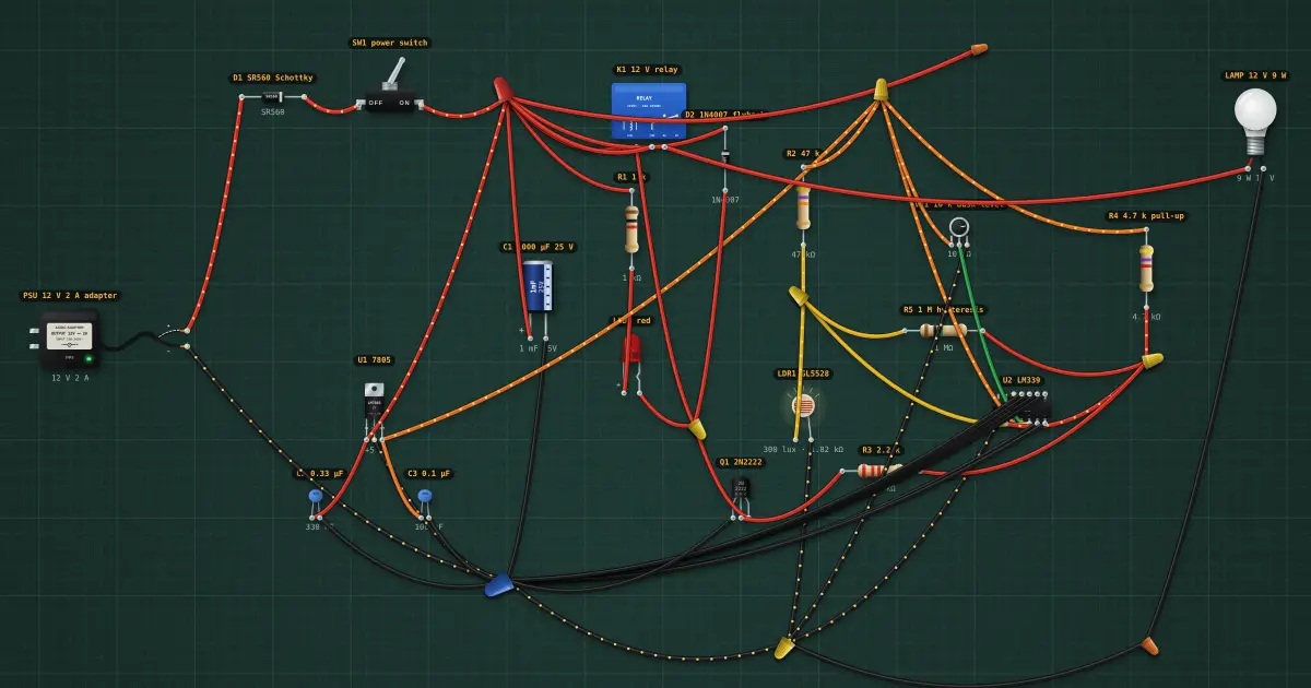
Step 10 of the automatic light: K1’s coil sits where the LED was, between + and Q1; D2 across it. Its contacts switch a 12 V 9 W LED lamp straight from the supply. LED1 stays as the indicator next to the coil. Component 10 of 14: the relay (and a flyback diode). A relay is a switch worked by an electromagnet: a small coil current (30 mA here) closes contacts that can carry amps, fully isolated from the coil. When the coil is switched off its magnetic field collapses and kicks back a high voltage: a diode across the coil (flyback diode) catches it, or it kills the transistor.
Build it in the labGuided build, test sheet and fault finding, free in your browser.
Parts list
- DC adapter
- Schottky diode
- Toggle switch
- Electrolytic capacitor
- 5 × Resistor
- LED
- 7805 regulator
- 2 × Ceramic capacitor
- Photoresistor (LDR)
- NPN transistor
- LM339 quad comparator
- Potentiometer
- Relay
- Rectifier diode
- 12 V DC LED bulb
Test procedure
Each test has an expected value and a pass range, like a factory test sheet:
- Dark: lamp on
- Daylight: lamp off
- Coil current
How it works
The relay (and a flyback diode). A relay is a switch worked by an electromagnet: a small coil current (30 mA here) closes contacts that can carry amps, fully isolated from the coil. When the coil is switched off its magnetic field collapses and kicks back a high voltage: a diode across the coil (flyback diode) catches it, or it kills the transistor.
Reading it. Coil voltage (12 V DC) and contact rating (10 A 250 V AC) on the case. Pins: two coil, COM, NO (normally open, closes when energised), NC (normally closed). The flyback diode goes cathode to the coil’s + end.
Testing it. Ω across the coil: about 400 Ω for a 12 V coil. Continuity COM–NC when off; power the coil and hear the click, then COM–NO beeps.
In the build. K1’s coil sits where the LED was, between + and Q1; D2 across it. Its contacts switch a 12 V 9 W LED lamp straight from the supply. LED1 stays as the indicator next to the coil.
Builds on lesson 9: everything from before is still there.
Next: lesson 11, pir motion sensor.
Things to try
- Delete D2 and switch the relay off (make it bright): look at Q1’s collector voltage spike and its status.
- Meter the lamp current: 0.75 A that Q1 never has to carry.
Background
One circuit, built up one part at a time: by lesson 14 it is a solar-powered, dusk-sensing, motion-triggered timed lamp with an alarm.