Home UPS on a 24 V LiFePO4 battery: charger, inverter, changeover relays, two 220 V outputs
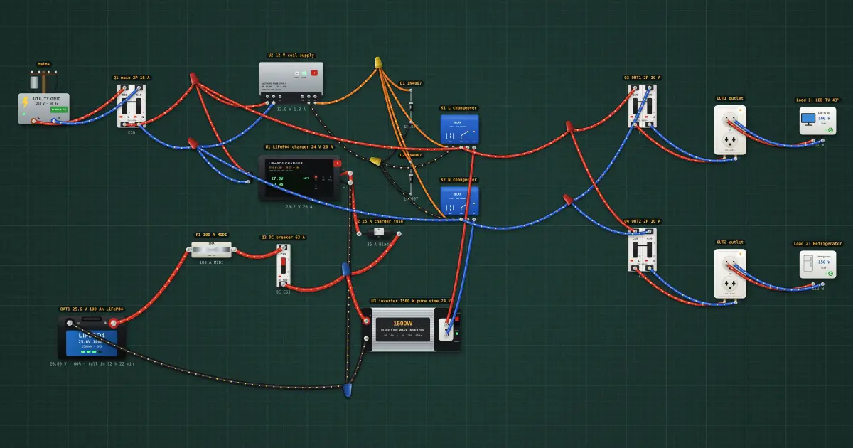
Keeps two 220 V circuits powered through outages from a 24 V LiFePO4 battery; charges from the grid when it returns. A line-interactive (stand-by) UPS from parts, on a 25.6 V 100 Ah LiFePO4 battery with its own BMS. How it works: U3, a 1500 W pure-sine inverter, runs all the time from the battery. U1 keeps the battery full from the grid (CC/CV for LiFePO4, 20 A, then float). K1 and K2 are changeover relays, one for L and one for N: their coils are held in by U2, a small 12 V supply fed from the grid, so while the grid is there the outputs take it from the NO contacts; when the grid fails U2 stops, the relays drop out, and the NC contacts hand the outputs to the inverter. Both wires are switched, so the grid and the inverter are never connected to each other, not even the neutral. D1/D2 absorb the coils’ kick. Outputs: two circuits, each on its own 2-pole 10 A breaker (Q3, Q4) feeding a duplex 220–240 V outlet: four sockets, 2.2 kW per circuit from the grid, 1500 W in total from the inverter. DC side: F1 100 A MIDI right at the battery + (it protects the cable), Q2 63 A DC breaker as the battery isolator, 8 AWG (8 mm²) cable. At full inverter load the battery gives about 65 A: a comfortable current for 8 AWG and a 63 A breaker. Transfer time: a relay changeover takes about 20–40 ms. TVs, fridges, routers, fans and lights ride through it; a desktop PC may reboot. For a PC, put it on an online UPS or a hybrid inverter in UPS mode (about 10 ms). Safety: the grid L and N must reach the outlets only through K1/K2, never in parallel with the inverter; earth the outlets’ ground pins and the inverter chassis to the house earth; keep the DC fuse within 30 cm of the battery terminal; LiFePO4 cells need compression and the BMS balance leads on the right cells (B1 between cells 1 and 2 and so on). The same build at 12 V and 48 V is on the Benches menu (“Home UPS 12 V…”, “Home UPS 48 V…”).
Build it in the labGuided build, test sheet and fault finding, free in your browser.
Parts list
- LiFePO4 battery
- 2 × Fuse
- DC breaker
- Utility grid
- 3 × AC breaker
- LiFePO4 charger
- Switching power supply
- 2 × Relay
- 2 × Rectifier diode
- Power inverter
- 2 × Wall outlet
- 2 × Household appliance
Test procedure
Each test has an expected value and a pass range, like a factory test sheet:
- Grid on: the outputs run from the grid
- Grid on: the charger fills the battery
- Outage: both outputs move to the inverter
- On battery: battery current for 250 W of loads
- Grid back: the outputs return to the grid and charging resumes
- Overload on battery: rice cooker on OUT1 and a kettle on OUT2 during an outage
How it works
What it does: Keeps two 220 V circuits powered through outages from a 24 V LiFePO4 battery; charges from the grid when it returns.
Build it (guided or ready-made), then run its test procedure below. Every test has an expected value and a pass range, just like a factory test sheet.
Things to try
- Click the grid to make an outage and watch K1/K2 drop out and the inverter take over.
- Turn the fridge into a kettle during an outage: the inverter overloads and shuts down.
- Open the 12 V and 48 V versions from the Benches menu and compare the battery currents.
Background
This is how most home “inverter + battery” backup systems in the Philippines are wired: a charger, an inverter and an automatic transfer switch, now on LiFePO4 instead of lead-acid.