3S LiFePO4 BMS
small 3S 9.6 V LiFePO4 board (LiFePO4 protection ICs, balancing near full) · 3S LiFePO4 · 5 A continuous, trips at about 8 A (10 ms), short circuit about 40 A (300 µs) · over-charge 3.75 V/cell (11.25 V pack), over-discharge 2.1 V/cell (6.3 V pack) · balancing 40 mA from 3.6 V
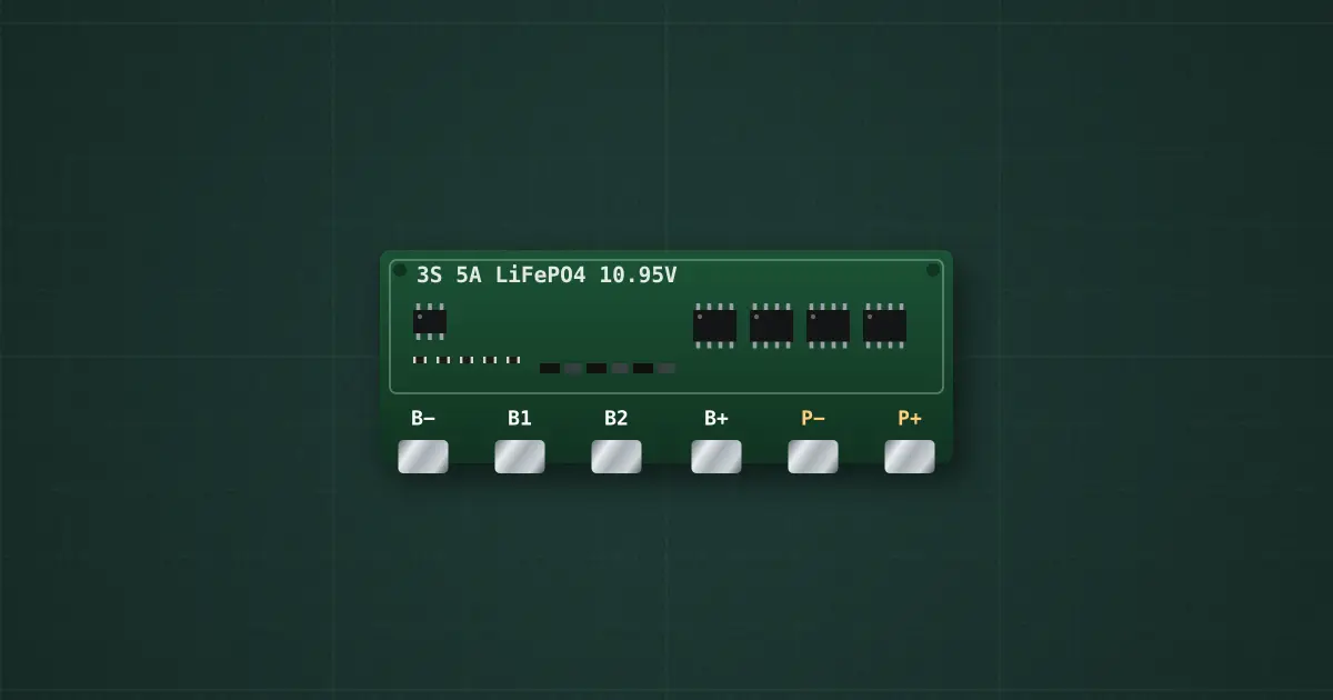
Try it on the benchThe lab drops it on an empty bench and opens its datasheet card.
Typical part: 3S LiFePO4 BMS — modelled on small 3S 9.6 V LiFePO4 board (LiFePO4 protection ICs, balancing near full)
Pins
- B−
- B1
- B2
- B+
- P−
- P+
Ratings and limits
| Protection | LiFePO4 protection IC (HY2112 type) + MOSFETs |
|---|---|
| Cells | 3S LiFePO4 |
| Over-charge | 3.75 V per cell after 1 s · release 3.6 V |
| Over-discharge | 2.1 V per cell after 100 ms · release: connect a charger (or the cells recover above 2.6 V) |
| Discharge current | 5 A continuous · over-current trip about 8 A after 10 ms |
| Short circuit | about 40 A · 300 µs · release: remove the load |
| MOSFET resistance | 30 mΩ (150 mV and 750 mW at 5 A) |
| Balancing | passive, 40 mA from 3.6 V |
| Temperature protection | none: above its continuous rating it heats, and its MOSFETs can fail shorted |
How to use it
Every cell junction gets a balance wire (B−, B1, B2, B+); the charger and the load connect only to P+ and P−.
More in charging & bms
- LiFePO4 charger
- TP4056 charger module
- TP5000 charger module
- 1S protection board
- 1S 10 A protection board
- 2S BMS
- 3S BMS
- 3S 40 A BMS
- 4S Li-ion BMS
- 6S Li-ion BMS
Sources: Typical 3S LiFePO4 BMS boards (protection IC + MOSFETs) and LiFePO4 cell limits (3.65 V max, 2.5 V min).