8S LiFePO4 BMS 100 A
Daly 8S 100 A LiFePO4 common-port · 8S LiFePO4 · 100 A continuous, trips at about 300 A (1 ms), short circuit about 600 A (250 µs) · over-charge 3.75 V/cell (30.00 V pack), over-discharge 2.5 V/cell (20.0 V pack) · balancing 30 mA from 3.5 V
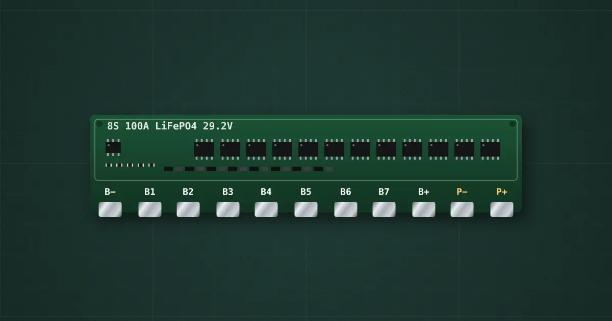
Try it on the benchThe lab drops it on an empty bench and opens its datasheet card.
Typical part: 8S LiFePO4 BMS 100 A — modelled on Daly 8S 100 A LiFePO4 common-port
Pins
- B−
- B1
- B2
- B3
- B4
- B5
- B6
- B7
- B+
- P−
- P+
Ratings and limits
| Protection | Daly standard LiFePO4 BMS |
|---|---|
| Cells | 8S LiFePO4 |
| Over-charge | 3.75 V per cell after 1 s · release 3.65 V |
| Over-discharge | 2.5 V per cell after 1 s · release: connect a charger (or the cells recover above 2.7 V) |
| Discharge current | 100 A continuous · over-current trip about 300 A after 1 ms |
| Short circuit | about 600 A · 250 µs · release: remove the load |
| MOSFET resistance | 1.5 mΩ (150 mV and 15 W at 100 A) |
| Balancing | passive, 30 mA from 3.5 V |
| Temperature protection | none: above its continuous rating it heats, and its MOSFETs can fail shorted |
How to use it
Wire B− to the pack’s negative end, B1…B7 to each junction between cells in order, B+ to the positive end. The load and charger go on P+ and P−: the board switches the negative side with back-to-back MOSFETs. Connect the balance leads in order, B− first: a lead connected out of order can destroy the board.
Lessons and builds that use it
- Home UPS on 8 × 3.2 V LiFePO4 cells + BMS: charger, inverter, changeover relays, two 220 V outputs (build)