Keypad door lock
Opens a servo bolt for the right code; buzzes and locks out after wrong ones. A 4×4 keypad is 16 switches on 8 wires. The sketch drives one row LOW at a time and reads the four columns with pull-ups: a pressed key pulls its column LOW in its row’s turn. Type 2580 and # and the servo pulls the bolt open for 5 s; three wrong codes lock the keypad for 30 s. The code is a number in the sketch: on a real door, keep it in EEPROM and let the owner change it. On the real thing: an SG90 on the Uno’s 5 V pin is fine on USB, but if the board resets when the bolt moves, give the servo its own 5 V supply (grounds joined). The LCD backpack is at 0x27 or 0x3F: run an I²C scanner if the screen stays blank.
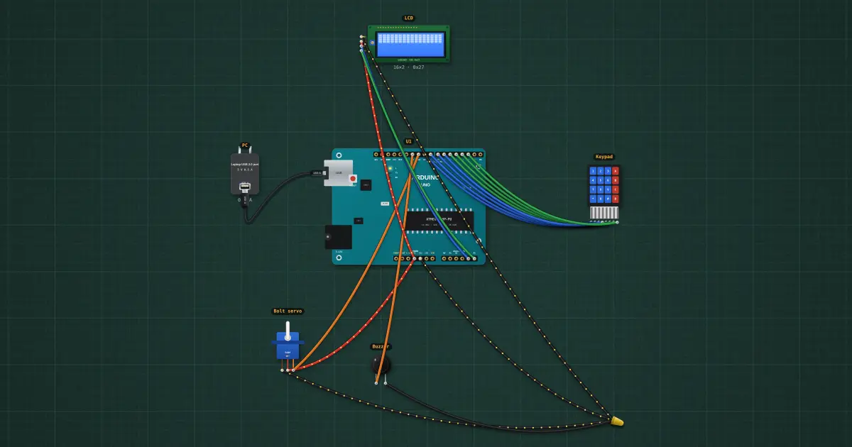
Build it in the labGuided build, test sheet and fault finding, free in your browser.
Parts list
Test procedure
Each test has an expected value and a pass range, like a factory test sheet:
- The right code opens it
- It locks itself again
- A wrong code is refused
How it works
What it does: Opens a servo bolt for the right code; buzzes and locks out after wrong ones.
Build it (guided or ready-made), then run its test procedure below. Every test has an expected value and a pass range, just like a factory test sheet.
Things to try
- Change CODE to your own four digits and upload.
- Press a key and watch the row pins on a scope: each row goes LOW in turn, thousands of times a second.
- A servo is not a lock: anyone can push it back. Real doors use a solenoid bolt or an electric strike, switched through a relay or a MOSFET.
Background
Push-button combination locks (Simplex, 1960s) became electronic keypads on alarms, safes and hotel doors in the 1980s.