NAND as a universal gate
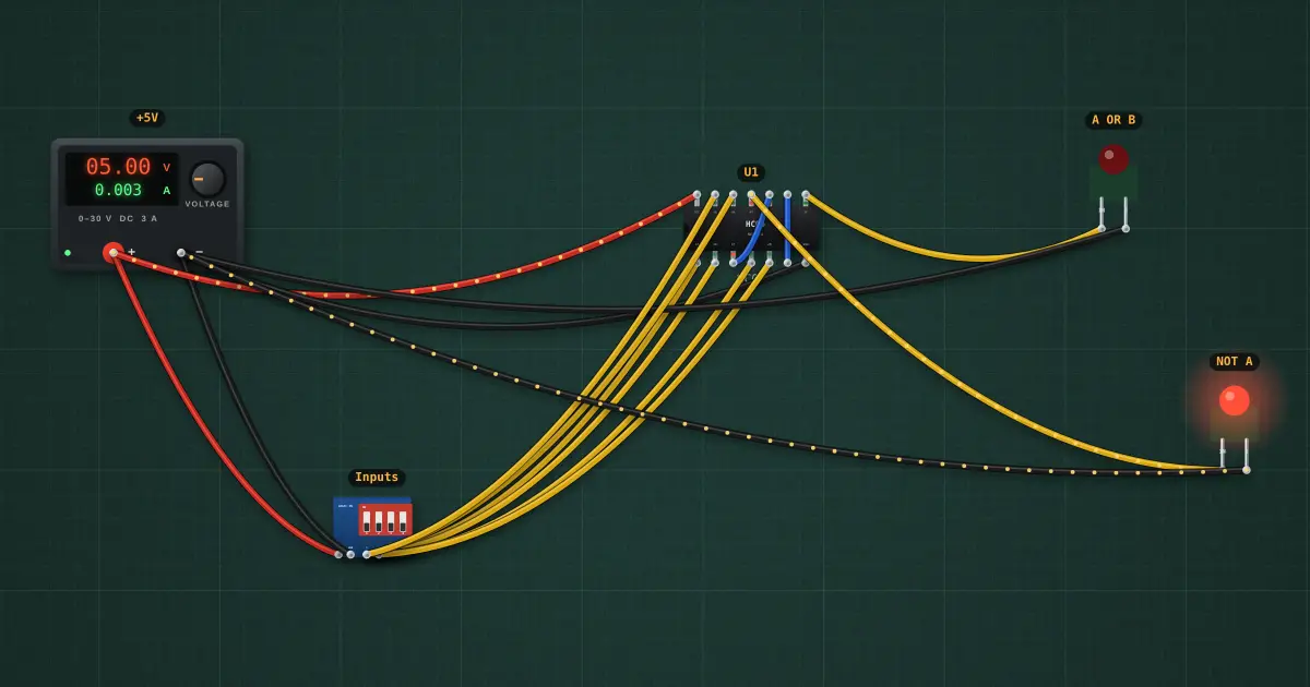
Using only NAND gates you can make NOT, AND and OR, and therefore any logic circuit. Here one 74HC00 makes NOT A (a NAND with its inputs tied together) and A OR B (inverting both inputs, then NANDing them: De Morgan’s law).
Open this lesson in the labFree, in your browser, no account needed.
How it works
NOT A = (A · A)̅ · A + B = (A̅ · B̅)̅ (De Morgan)
| A | B | A+B | A̅ | bench | |
|---|---|---|---|---|---|
| 0 | 0 | 0 | 1 | — | |
| 0 | 1 | 1 | 1 | — | |
| 1 | 0 | 1 | 0 | — | |
| 1 | 1 | 1 | 0 | — |
Flip the switches to try every row. “bench” fills in with what the chip actually did.
Gates 1 and 2 invert A and B, gate 3 NANDs the results, which gives OR. Gate 4 on its own is a NOT. AND would be NAND followed by a NAND-inverter.
Try it on the bench
- Step through all four input combinations and check the OR column fills exactly like a real OR gate.
- Follow the blue wires: each one carries an inverted input into the last NAND.
Parts on the bench
- Bench power supply
- DIP switch module
- 74xx00
- 2 × Logic indicator LED
In the course
Zen’s Electronics Design Mastery, module “Digital Electronics”.