SR latch (memory from two gates)
Feed two NOR gates’ outputs back into each other and the circuit remembers. A pulse on S (set) makes Q = 1, a pulse on R (reset) makes Q = 0, and with both inputs at 0 it holds whatever it last had. That is one bit of memory.
Open this lesson in the labFree, in your browser, no account needed.
How it works
Q = (R + Q̅)̅ · Q̅ = (S + Q)̅
| S | R | meaning | bench Q Q̅ |
|---|---|---|---|
| 0 | 0 | hold: Q stays as it was | — |
| 1 | 0 | set: Q = 1 | — |
| 0 | 1 | reset: Q = 0 | — |
| 1 | 1 | not allowed: Q = Q̅ = 0 | — |
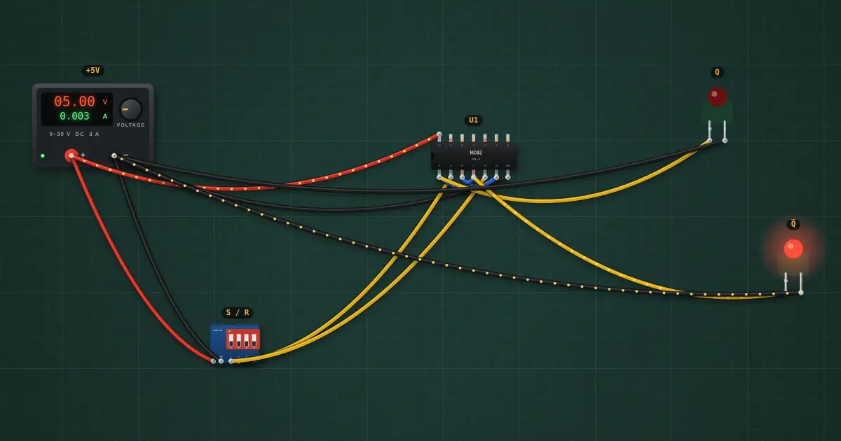
Switch 1 is S, switch 2 is R. The output depends on the past, not only on the inputs now: that is the difference between sequential and combinational logic.
Try it on the bench
- Flip S on then off: Q stays 1 after S goes back to 0. The latch remembers.
- Now flip R on then off: Q drops to 0 and stays there.
- Turn on both S and R, then turn both off at once. Which way it falls is a race between the two gates, which is why S = R = 1 is forbidden.
Parts on the bench
- Bench power supply
- DIP switch module
- 74xx02
- 2 × Logic indicator LED
In the course
Zen’s Electronics Design Mastery, module “Digital Electronics”.