2-to-1 multiplexer
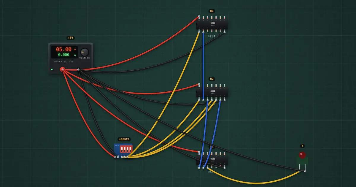
A multiplexer is a digital selector switch. With S = 0 the output copies input A, with S = 1 it copies input B. Y = A·S̅ + B·S. It routes data, and a bank of them makes a CPU’s data paths.
Open this lesson in the labFree, in your browser, no account needed.
How it works
Y = A·S̅ + B·S. Switch 1 is A, switch 2 is B, switch 3 is the select line S.
| S | A | B | Y | bench | |
|---|---|---|---|---|---|
| 0 | 0 | 0 | 0 | — | |
| 0 | 0 | 1 | 0 | — | |
| 0 | 1 | 0 | 1 | — | |
| 0 | 1 | 1 | 1 | — | |
| 1 | 0 | 0 | 0 | — | |
| 1 | 0 | 1 | 1 | — | |
| 1 | 1 | 0 | 0 | — | |
| 1 | 1 | 1 | 1 | — |
Flip the switches to try every row. “bench” fills in with what the chip actually did.
Try it on the bench
- Set A = 1 and B = 0, then flip S: the output follows whichever input S selects.
- A 74HC157 packs four of these into one chip, sharing one select line.
Parts on the bench
- Bench power supply
- DIP switch module
- 74xx04
- 74xx08
- 74xx32
- Logic indicator LED
In the course
Zen’s Electronics Design Mastery, module “Digital Electronics”.