JK flip-flop
The JK flip-flop fixes the SR latch’s forbidden state. On each falling clock edge: J sets, K resets, both 0 holds, and both 1 toggles. Toggling halves the clock frequency, which is the basis of counters.
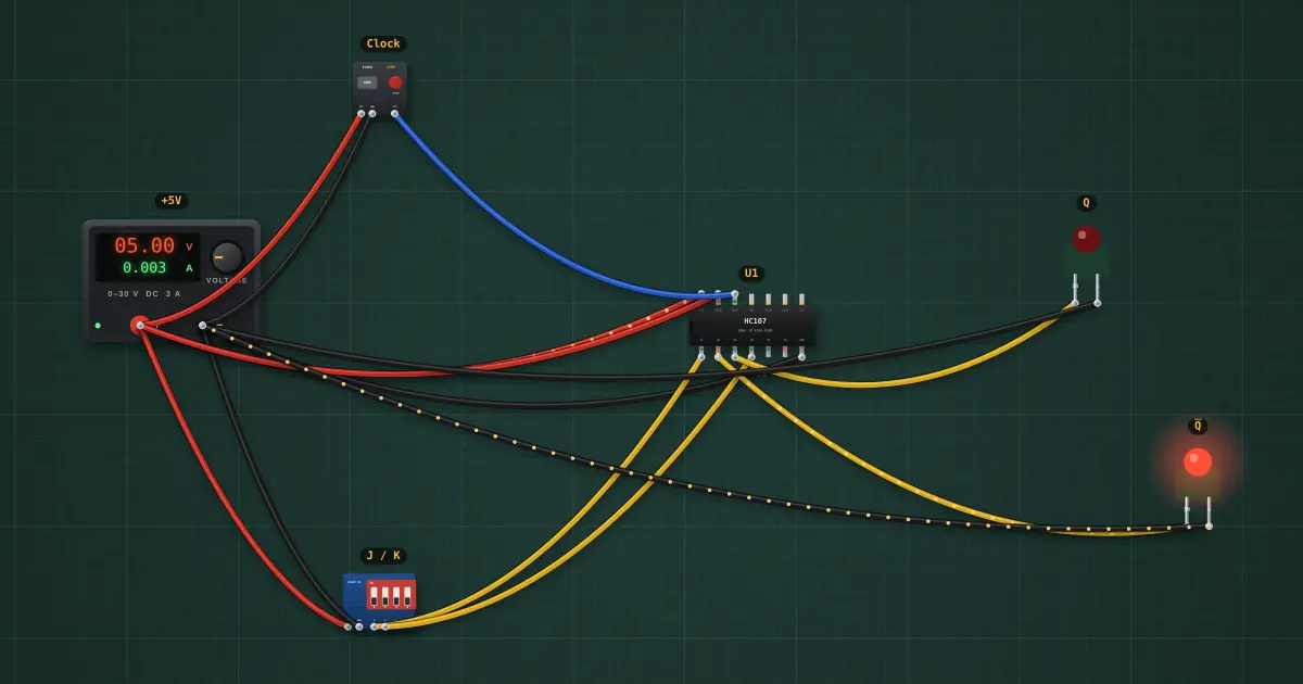
Open this lesson in the labFree, in your browser, no account needed.
How it works
On each falling clock edge (↓):
| J | K | Q next |
|---|---|---|
| 0 | 0 | Q (hold) |
| 0 | 1 | 0 (reset) |
| 1 | 0 | 1 (set) |
| 1 | 1 | Q̅ (toggle) |
Falling edges so far: 0.
Try it on the bench
- Set J = K = 1 and pulse the clock: Q toggles on each pulse. It changes when the button is released, on the falling edge.
- Set the clock to RUN at 2 Hz with J = K = 1: Q blinks at 1 Hz, half the clock rate.
Parts on the bench
- Bench power supply
- DIP switch module
- Clock / pulse generator
- 74xx107
- 2 × Logic indicator LED
In the course
Zen’s Electronics Design Mastery, module “Digital Electronics”.