Shift register (74HC164)
A shift register is a row of D flip-flops sharing one clock, each feeding the next. Every clock edge moves the stored bits one place along and takes a new bit in at the start. It turns serial data (one wire) into parallel data (eight wires).
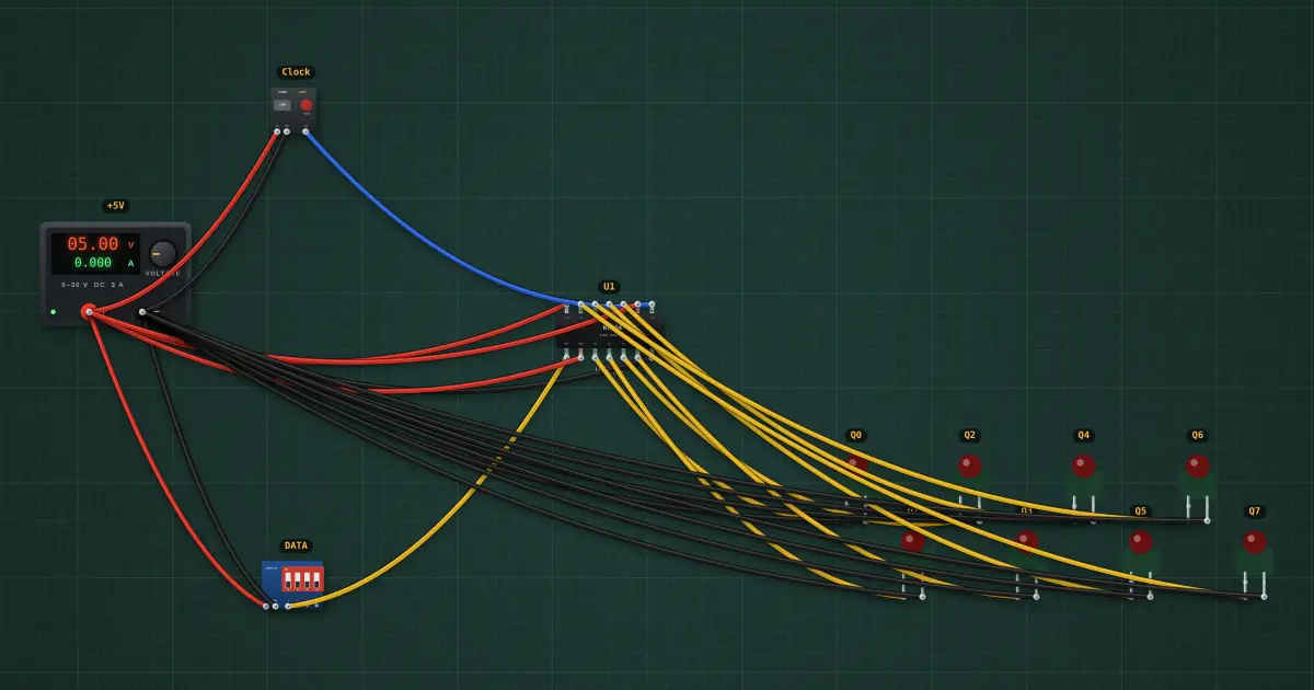
Open this lesson in the labFree, in your browser, no account needed.
How it works
On each rising clock edge: Q7 ← Q6 ← … ← Q1 ← Q0 ← DATA.
········
Q0 → Q7, left to right. Eight clocks shift a whole byte in through one wire. The 74HC595 adds an output latch and drives LED matrices and displays this way.
Try it on the bench
- Set DATA = 1 and pulse the clock once: Q0 lights. Set DATA = 0 and keep pulsing: the lit bit walks along the row.
- Switch the clock to RUN at 2 Hz and flip DATA to draw patterns.
Parts on the bench
- Bench power supply
- DIP switch module
- Clock / pulse generator
- 74xx164
- 8 × Logic indicator LED
In the course
Zen’s Electronics Design Mastery, module “Digital Electronics”.