Victron SmartSolar MPPT 100/30 guide
A small MPPT charge controller for a 12 V or 24 V battery: an RV, a boat, a cabin or a small DIY system. It picks 12 V or 24 V by itself at first power-up and is set up over Bluetooth with the phone app.
Simulate this kind of system ▸Check my panels for this model
Key ratings
| Battery voltage | 12 V or 24 V (auto select) |
|---|---|
| Rated charge current | 30 A |
| Nominal PV power | 440 W at 12 V, 880 W at 24 V |
| Max PV open-circuit voltage | 100 V |
| Max PV short-circuit current | 35 A |
| Max efficiency | 98 % |
| Start-up | PV must be about 5 V above the battery to start, then 1 V above to keep going |
100 V is the hard limit, including on the coldest morning. With 12 V-type panels that is three in series at most; larger 40–50 V panels go in parallel instead.
Which system it builds
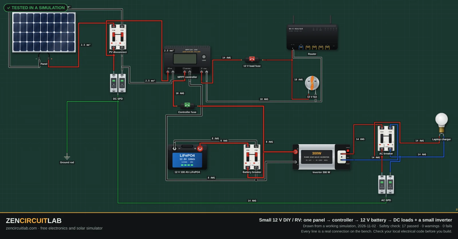
This unit is the heart of the lab's 12 V solar system for an RV, boat or small DIY: panels, the charge controller, a battery and the loads, with the protection in between.
How many panels in series
With a typical 200 W "12 V" panel (Voc 24.6 V, Vmp 20.6 V, -0.3 %/°C): on a 15 °C morning each panel reaches 25.3 V, so at most 3 in series stay under 100 V (3 on a −5 °C morning). On a hot roof each panel's Vmp falls to about 17.8 V. For a 12 V battery use 2 in series; for 24 V use 2 or 3 in series so the string stays well above the battery. Add strings in parallel up to about 440 W at 12 V or 880 W at 24 V; more panels only clip at 30 A.
Open the string calculator with the Victron SmartSolar MPPT 100/30 limits filled in →
Battery, fuse and cable
The controller charges at up to 30 A: use a 40 A fuse or breaker between controller and battery, close to the battery, and cable rated for it (6 mm² / 10 AWG for short runs).
Wiring order
- Mount the unit on a non-flammable wall with the clearances in the manual, close to the battery (short battery cables).
- Battery first, with every breaker open: a 12 V battery, a DC breaker or fuse of about 40 A in the positive cable (full output is about 30 A at 12 V), and the cable size the manual gives for that current. Check polarity twice: reversed battery cables destroy most inverters.
- Connect the controller to the battery before the panels, so it detects 12 V or 24 V correctly.
- Panels last, with the PV isolator open: measure the string's open-circuit voltage with a meter before closing it, and compare it with the limit above.
- Power up in order: battery breaker, then the PV isolator. Set the battery type before the first charge.
Settings to check
- Battery type: lithium (LiFePO4) or the lead-acid preset. Typical 12 V LiFePO4: absorption 14.2–14.4 V, float 13.5 V; 24 V: double these.
- Load output or relay, if used, and low-voltage disconnect.
- Pair the phone app (Bluetooth) and check the battery voltage it reads against a meter.
⚠ This is a design aid to learn from and plan with, not the maker's instructions. Read the manual, follow your local electrical code, and have mains and battery wiring checked by a qualified electrician.
Questions
How many solar panels can I connect to the Victron SmartSolar MPPT 100/30?
About 440 W at 12 V or 880 W at 24 V, with the open-circuit voltage of each series string under 100 V on the coldest morning. With 200 W panels that is two in series for 12 V, and up to three in series for 24 V.
What battery does the Victron SmartSolar MPPT 100/30 need?
A 12 V or 24 V battery: lead-acid or LiFePO4. It charges at up to 30 A.
Is this an official guide?
No. It is an independent guide by Zen Circuit Lab, worked out from the published specifications (sources below). Ratings can change between hardware versions: the label on your unit and its manual always win.
Sources
Other guides
Growatt SPF 5000 ES · Deye SUN-5K-SG03LP1 · Luxpower SNA 5000 · PowMr POW-HVM3.2H-24V-N (3 kW 24 V) · All model guides