Reading colour codes and markings
Every part carries its value: colour bands on resistors, a three-digit code on ceramic capacitors (two digits and a number of zeros, in picofarads), printed values on electrolytics. Read the marking, then confirm it with a meter: a technician never trusts either alone.
Open this lesson in the labFree, in your browser, no account needed.
How it works
Four-band code: digit, digit, multiplier, tolerance. Black 0, brown 1, red 2, orange 3, yellow 4, green 5, blue 6, violet 7, grey 8, white 9; gold multiplier ÷10, gold tolerance ±5 %.
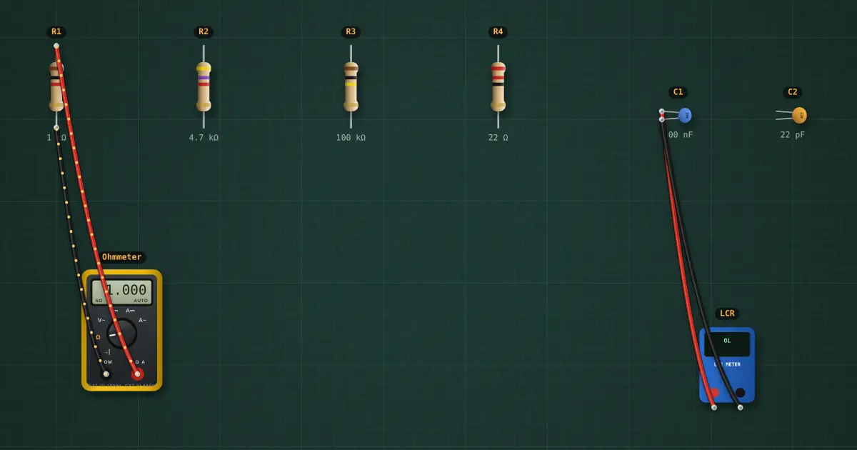
R1 brown-black-red = 1 kΩ · R2 yellow-violet-red = 4.7 kΩ · R3 brown-black-yellow = 100 kΩ · R4 red-red-black = 22 Ω.
Ceramic codes are in pF: 104 = 10 × 10⁴ pF = 100 nF; a plain “22” is 22 pF.
Try it on the bench
- Drag the meter’s leads from R1 to R4: 22 Ω has a black third band, multiplier ×1.
Parts on the bench
- 4 × Resistor
- Digital multimeter
- 2 × Ceramic capacitor
- LCR meter
In the course
Electronics Fundamentals, module “Voltage, current and resistance”.