SPI bus: MAX7219 display
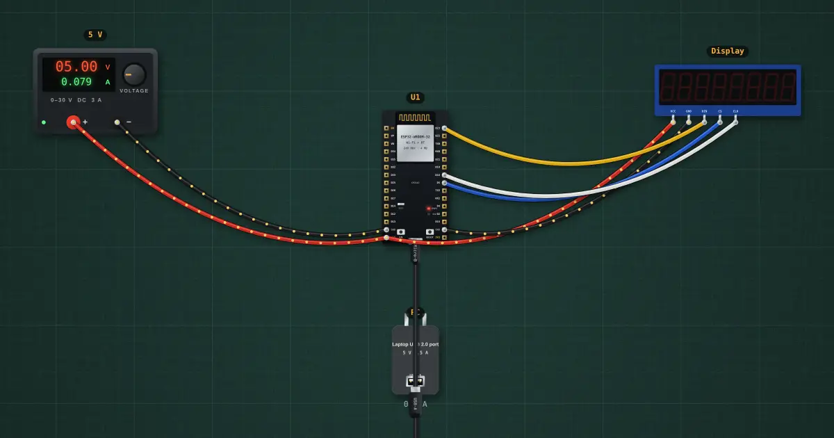
SPI is the other main serial bus. The master drives a clock (SCK) and shifts data out on MOSI while each device has its own chip-select (CS) line, pulled low to talk to it. It is fast and simple, but needs a CS wire per device, where I²C uses addresses on two shared wires.
Open this lesson in the labFree, in your browser, no account needed.
How it works
Each update is a 16-bit frame: CS low, register address byte, data byte, CS high. The rising edge of CS latches the frame into the MAX7219.
Registers 1–8 hold the eight digits, 0x09 turns on BCD decoding, 0x0A sets brightness, 0x0B how many digits to scan, 0x0C wakes it from shutdown.
Frames received: 0.
Try it on the bench
- Swap the DIN and CLK wires: frames still go out but the display shows nothing useful. SPI needs every line right.
- Edit send(0x0A, 8) to 15 for full brightness, or 1 for dim.
- Add a second MAX7219 with its own CS on GPIO15: both share SCK and MOSI.
Parts on the bench
- Bench power supply
- ESP32 DevKit
- USB charger / port
- MAX7219 8-digit display
In the course
Zen’s Electronics Design Mastery, module “Microcontrollers & Embedded”.