ESP32 DevKit (ESP32-WROOM-32, AMS1117)
ESP32-WROOM-32 DevKit V1 · 30 pins · 3.3 V logic · VIN 5 V through AMS1117
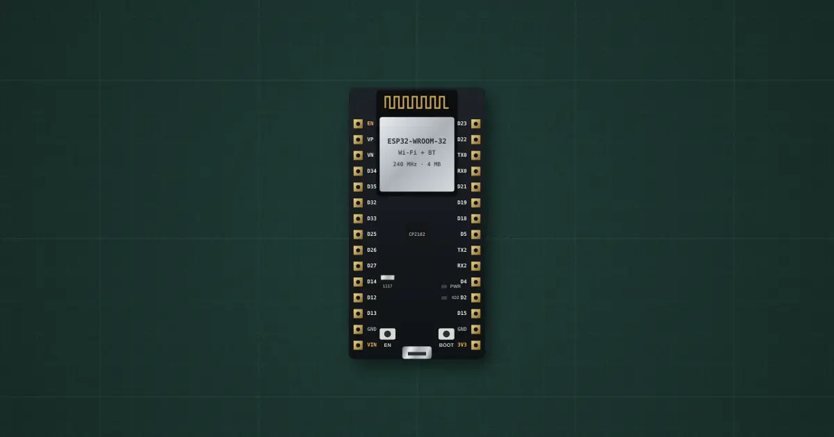
Try it on the benchThe lab drops it on an empty bench and opens its datasheet card.
Typical part: ESP32-WROOM-32 on a DevKit V1 board
Pins
- EN
- VP
- VN
- D34
- D35
- D32
- D33
- D25
- D26
- D27
- D14
- D12
- D13
- GND
- VIN
- D23
- D22
- TX0
- RX0
- D21
- D19
- D18
- D5
- TX2
- RX2
- D4
- D2
- D15
- GND
- 3V3
- Micro-USB port
Ratings and limits
| Supply | 5 V on VIN or USB, through an AMS1117 to 3.3 V. VIN up to 15 V, but the AMS1117 gets hot long before (5 mA of its own, 1.1 V dropout at 800 mA, shuts down at 165 °C: AMS1117 datasheet) |
|---|---|
| Logic levels | LOW below 0.25 × 3.3 V = 0.83 V, HIGH above 0.75 × 3.3 V = 2.48 V (WROOM-32 datasheet, DC characteristics) |
| Pin current | about 20 mA at the default drive strength; 40 mA source / 28 mA sink at full drive; 1100 mA for all pins together (WROOM-32 datasheet) |
| Pull resistors | 45 kΩ up or down on every pin that can output; none on GPIO34–39, which are inputs only |
| ADC | 12-bit, ADC1 on GPIO32–39 and ADC2 on 0, 2, 4, 12–15, 25–27. At 11 dB (the default) it reads 150–2450 mV in a straight line and stops near 3.1 V; ±60 mV after calibration, about ±6 % without (ESP32 datasheet). ADC2 cannot be used while Wi-Fi is on |
| Strapping pins | read at reset: GPIO0 (BOOT button: run or download), GPIO2 (low for download), GPIO5, GPIO12 (HIGH = 1.8 V flash: the WROOM-32 then will not boot), GPIO15 (LOW = no boot log) |
| Current | chip: about 45 mA running, 100 mA with Wi-Fi on, 240 mA transmitting, 10 µA in deep sleep (ESP32 datasheet). This board adds a power LED (about 0.75 mA through 2 kΩ), the CP2102 USB chip (20 mA with a computer attached, 80 µA otherwise) and the AMS1117’s 5 mA when fed through VIN |
| PWM (LEDC) | 16 channels; duty resolution at most log2(80 MHz ÷ frequency) bits, and never more than 20 (ESP32 datasheet / Arduino-ESP32 LEDC API) |
| DAC, touch | two 8-bit DACs on GPIO25 and GPIO26; touch pins T0–T9 on GPIO4, 0, 2, 15, 13, 12, 14, 27, 33, 32 |
How to use it
Wi-Fi/Bluetooth microcontroller for IoT nodes. Never feed 5 V into a GPIO, keep pull-ups off GPIO12, and read voltages with analogReadMilliVolts(). Sources: ESP32 Series datasheet, ESP32-WROOM-32 datasheet, ESP32-DevKitC V4 schematic, AMS1117 and CP2102 datasheets (Espressif, Advanced Monolithic Systems, Silicon Labs).
Lessons and builds that use it
- Interrupts and debouncing
- Deep sleep and battery life
- Settings that survive a reset (NVS)
- Watchdog timer
- SPI bus: MAX7219 display
- I²C sensor: accelerometer tilt
- I²C sensor: temperature, humidity, pressure
- PWM actuator: hobby servo
- PWM actuator: DC motor through a MOSFET
- Monitoring a supply rail with the ADC
- Sensor-to-cloud signal pipeline
- Detecting USB plug-in with an ESP32
- Blink: your first sketch
- Analog in, PWM out