PWM actuator: DC motor through a MOSFET
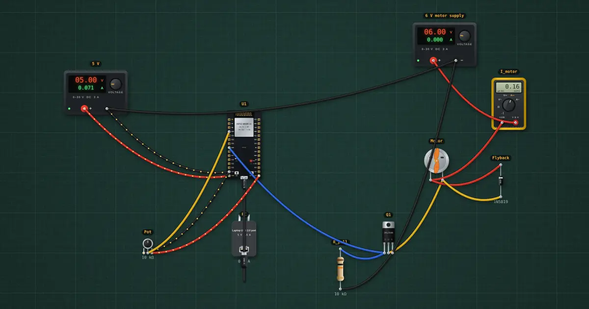
A GPIO pin gives a few milliamps; a motor wants an amp. A logic-level MOSFET switches the motor’s own supply, and PWM sets the average voltage: at duty d the motor sees d × V. The diode across the motor carries its current when the MOSFET switches off, so the inductive kick never reaches the MOSFET.
Open this lesson in the labFree, in your browser, no account needed.
How it works
Duty d = 54 % → average motor voltage ≈ d × 6 V = 3.22 V
Average current ≈ d × V / Rmotor = 527.6 mA (the motor is about 6 Ω here; RDS(on) at 3.3 V gate is 54 mΩ)
The simulator averages the 20 kHz switching; on a scope the drain would be a 20 kHz square wave. The 10 kΩ pull-down keeps the motor off while the ESP32 boots and its pins float.
Try it on the bench
- Scroll over the pot to change the duty: the motor current and speed follow.
- Delete the flyback diode. In a real circuit every switch-off now slams the MOSFET with a voltage spike (see the inductive-load lesson).
- Set the duty to 100 %: the MOSFET is fully on and dissipates only milliwatts.
Parts on the bench
- 2 × Bench power supply
- ESP32 DevKit
- USB charger / port
- Digital multimeter
- DC motor
- Schottky diode
- N-channel MOSFET
- Resistor
- Potentiometer
In the course
Zen’s Electronics Design Mastery, module “Microcontrollers & Embedded”.