Raspberry Pi Pico 2 (RP2350A, RT6154A, RP2350)
Raspberry Pi Pico 2 · RP2350A dual Cortex-M33 (or Hazard3 RISC-V) at 150 MHz · 520 KB SRAM · 4 MB flash · 26 GPIO (3.3 V, 5 V-tolerant inputs except ADC) · 3 × 12-bit ADC + VSYS/3 · 2 UART, 2 SPI, 2 I²C, 24 PWM, 3 PIO · Micro-USB · VSYS 1.8–5.5 V → RT6154A buck-boost → 3.3 V · no wireless
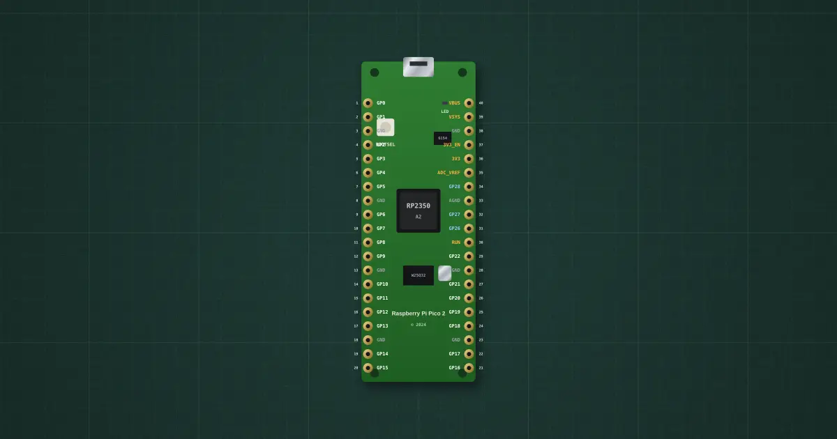
Try it on the benchThe lab drops it on an empty bench and opens its datasheet card.
Typical part: Raspberry Pi Pico 2 (RP2350A, 4 MB flash)
Pins
- RUN (pin 30)
- GP0 (pin 1)
- GP1 (pin 2)
- GP2 (pin 4)
- GP3 (pin 5)
- GP4 (pin 6)
- GP5 (pin 7)
- GND (pin 8)
- GP6 (pin 9)
- GP7 (pin 10)
- GP8 (pin 11)
- GP9 (pin 12)
- GND (pin 13)
- GND (pin 3)
- VSYS (pin 39)
- GP10 (pin 14)
- GP11 (pin 15)
- GP12 (pin 16)
- GP13 (pin 17)
- GND (pin 18)
- GP14 (pin 19)
- GP15 (pin 20)
- VBUS (pin 40)
- 3V3_EN (pin 37)
- ADC_VREF (pin 35)
- GP28 (pin 34)
- AGND (pin 33)
- GP27 (pin 32)
- GND (pin 38)
- 3V3(OUT) (pin 36)
- Micro-USB port (native USB: Serial / UF2 upload; VBUS → diode → VSYS)
- GP26 (pin 31)
- GP22 (pin 29)
- GND (pin 28)
- GP21 (pin 27)
- GP20 (pin 26)
- GP19 (pin 25)
- GP18 (pin 24)
- GND (pin 23)
- GP17 (pin 22)
- GP16 (pin 21)
- GP23 (SMPS power-save, internal)
- GP24 (VBUS sense, internal)
- GP25 (user LED, internal)
- GP29 / ADC3 (VSYS ÷ 3, internal)
- (unused)
- (unused)
Ratings and limits
| CPU | RP2350A: 2 × Arm Cortex-M33 or 2 × Hazard3 RISC-V (chosen at boot), 150 MHz, 520 KB SRAM, 4 MB QSPI flash on the board |
|---|---|
| Power | VSYS 1.8–5.5 V into an RT6154A buck-boost (3.3 V out, about 300 mA spare for your circuit on 3V3(OUT)). USB VBUS reaches VSYS through a Schottky diode. 3V3_EN low switches the regulator off |
| GPIO | 26 on the header (GP0–22, GP26–28), 3.3 V outputs about 4–12 mA (12 mA max drive), inputs 5 V tolerant when the board is powered, except GP26–29 |
| ADC | 12-bit SAR, 500 ksps, 4 inputs (GP26–28 on the header, GP29 = VSYS ÷ 3 inside) + temperature sensor; reference ADC_VREF ≈ 3.3 V; about 9 effective bits |
| Peripherals | 2 × UART, 2 × SPI, 2 × I²C, 24 PWM channels (12 slices: both pins of a slice share one frequency), 3 PIO blocks (12 state machines), USB 1.1 device/host |
| Board pins inside | GP23 SMPS power-save, GP24 VBUS sense, GP25 green LED, GP29 VSYS ÷ 3 |
| Boot | hold BOOTSEL at reset → USB drive "RP2350" for drag-and-drop .uf2; otherwise runs from flash. RUN low = reset |
| Current | about 20–25 mA running at 150 MHz (lab figure), a few mA in the bootloader |
How to use it
A bare-metal microcontroller: no operating system and no radio. Program it with the Arduino-Pico core (Serial over USB, Serial1/Serial2 on the UARTs, Wire, SPI, analogRead/analogWrite) or MicroPython. Compare with the ESP32 (a microcontroller with Wi-Fi) and the Orange Pi One (a Linux computer): same 3.3 V logic, three different software worlds.
More in microcontrollers & modules
- Arduino Uno R3
- Arduino Nano
- ESP32 DevKit
- ESP32-S3 DevKitC-1
- LILYGO T-SIM A7670E R2
- Orange Pi One
- Coin acceptor
- Coin slot (₱5 only)
- I2C LCD
- MAX7219 8-digit display
Sources: Raspberry Pi Pico 2 datasheet and RP2350 datasheet (Raspberry Pi Ltd, 2024); Arduino-Pico core documentation (pin defaults, analogRead/analogWrite, Serial1/Serial2 setTX/setRX, upload by UF2). PIO and MicroPython are not modelled in the lab yet.