LILYGO T-SIM A7670E R2 (ESP32-WROVER-E, ESP32)
LILYGO T-SIM A7670E R2 · ESP32-WROVER-E (240 MHz, 4 MB flash, 8 MB PSRAM, Wi-Fi + BLE) · SIMCom A7670E-LASE LTE Cat-1 (B1/B3/B5/B8/B20) with GSM/EDGE 900/1800 fallback, no GNSS · nano-SIM · 18650 holder + Li-ion charger · USB-C (CH9102) · modem on Serial1 RX 27 / TX 26, PWRKEY 4, POWERON 12, BAT_ADC 35
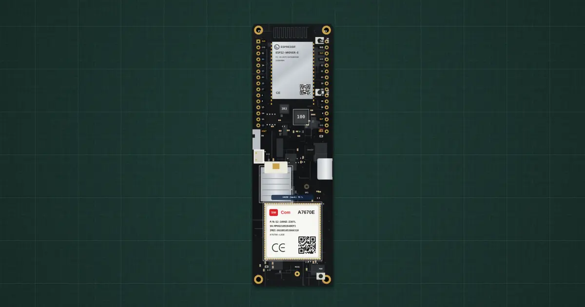
Try it on the benchThe lab drops it on an empty bench and opens its datasheet card.
Typical part: LILYGO T-SIM A7670E R2 (ESP32-WROVER-E + SIMCom A7670E)
Pins
- RST (EN)
- GPIO32
- GPIO33 · modem RI
- GPIO34 (input only)
- GPIO35 · BAT_ADC (VBAT ÷ 2)
- GPIO25 · modem DTR
- GPIO26 · MODEM_TX → A7670 RXD
- GPIO27 · MODEM_RX ← A7670 TXD
- GPIO4 · modem POWER key (HIGH presses PWRKEY)
- GPIO2 · TF card MISO
- GPIO15 · TF card MOSI
- GPIO14 · TF card SCLK
- GPIO13 · TF card CS
- GND
- VBUS (5 V from USB-C; or feed 5 V here)
- GPIO12 · modem supply EN (BOARD_POWERON)
- VBAT (18650 +, charger output, modem supply)
- TXD (GPIO1, Serial TX)
- RXD (GPIO3, Serial RX)
- 3V3
- GPIO22 · Wire SCL
- GPIO21 · Wire SDA
- GPIO23 · VSPI MOSI
- GPIO19 · VSPI MISO
- GPIO18 · VSPI SCK
- GPIO5 · modem RESET (HIGH resets) · VSPI CS
- GPIO39 (VN, input only)
- GPIO36 (VP, input only)
- GND
- 3V3
- USB-C (CH9102 USB-to-UART: Serial and upload; 5 V in)
- GPIO0 · BOOT strap (IO0 button)
- GND
- USB-C CC (5.1 kΩ to GND, inside)
- Modem VBAT (after the supply switch, inside)
- SOLAR + (PH2.0 JST, 4.4–6 V; − is GND)
- (unused)
- (unused)
- (unused)
- (unused)
- (unused)
- (unused)
- (unused)
- (unused)
- (unused)
Ratings and limits
| MCU | ESP32-WROVER-E: dual-core 240 MHz, Wi-Fi 802.11 b/g/n, BLE, 4 MB flash, 8 MB PSRAM (GPIO16/17 are the PSRAM’s) |
|---|---|
| Modem | SIMCom A7670E LTE Cat-1, LTE-FDD B1/B3/B5/B8/B20, GSM/GPRS/EDGE 900/1800. LTE 10 Mbps down / 5 Mbps up; EDGE 236.8 kbps. No GNSS on this variant (the A7670G has it) |
| Modem link | UART at 115200: Serial1.begin(115200, SERIAL_8N1, 27, 26). PWRKEY (GPIO4 HIGH presses it), BOARD_POWERON (GPIO12 HIGH switches the modem supply on), RESET (GPIO5 HIGH), DTR 25, RI 33 |
| Power-on | supply on (GPIO12), press PWRKEY (LILYGO: 100 ms to 1 s), then poll AT: about 3 s until it answers. A modem that browned out is off and needs PWRKEY again |
| Power | USB-C 5 V (CH9102 USB-to-UART) or 5 V on the header; 18650 holder with an on/off switch; Li-ion charger (lab: 500 mA, 4.2 V). The modem supply hangs on the battery node |
| Current | GSM transmit bursts about 2 A for 577 µs every 4.6 ms; LTE about 0.45 A while sending; idle registered about 25 mA (lab figures). Without the 18650, the charger and the board’s capacitance must supply the bursts |
| BAT_ADC | GPIO35 = battery ÷ 2 (100k / 100k): analogReadMilliVolts(35) × 2 |
| Size | 111 × 34 × 19 mm (with the 18650 holder), four 2 mm holes, 2 × 16 header at 2.54 mm, TF card slot and micro-USB (modem USB) on the back |
| Versions | Without GPS (A7670E-LASE, Q195) or with GPS (A7670E-FASE: GNSS inside the modem, ceramic patch antenna on the GPS u.FL, Q334). Read it with AT+CGNSSPWR=1, AT+CGNSSINFO, or NMEA with AT+CGNSSTST=1 |
How to use it
The real board behind a connected tracker: one ESP32 runs your sketch and drives an LTE modem over an internal UART, with a battery-backed supply for the modem’s transmit peaks. Pair it with a GY-NEO6MV2 for position, a TFT for the readout, and a protected LiFePO4 or 18650 rail.
Lessons and builds that use it
More in microcontrollers & modules
- Arduino Uno R3
- Arduino Nano
- ESP32 DevKit
- ESP32-S3 DevKitC-1
- Raspberry Pi Pico 2
- Orange Pi One
- Coin acceptor
- Coin slot (₱5 only)
- I2C LCD
- MAX7219 8-digit display
Sources: LILYGO wiki T-A7670E and the LilyGo-Modem-Series repository (utilities.h, pin map and power-on sequence); SIMCom A76xx AT command manual and hardware notes. Charger current, capacitance, LTE average current and the shutdown threshold are lab estimates.