Bridge rectifier and filter
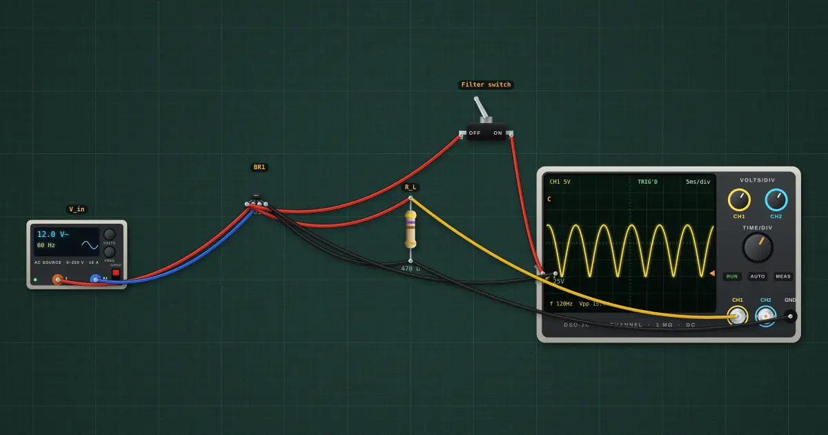
Four diodes steer both half-cycles the same way through the load, so nothing is wasted and the ripple runs at twice the mains frequency. The price is two diode drops instead of one.
Open this lesson in the labFree, in your browser, no account needed.
How it works
Output peak = Vpk − 2·VF ≈ 16.97 V − 2 × ~0.8 V = 15.4 V
Average ≈ 2(Vpk − 2VF) / π = 9.368 V, twice the half-wave figure, with a hump every 8.33 ms.
Try it on the bench
- Close the filter switch: a smooth DC line with a small 120 Hz ripple.
- Open the lesson “Half-wave rectifier” afterwards and compare the ripple for the same load and capacitor.
- This is the front end of most linear power supplies: transformer, bridge, reservoir capacitor, then a regulator.
Parts on the bench
In the course
Zen’s Electronics Design Mastery, module “Diodes & Power Supplies”.