Inverting amplifier
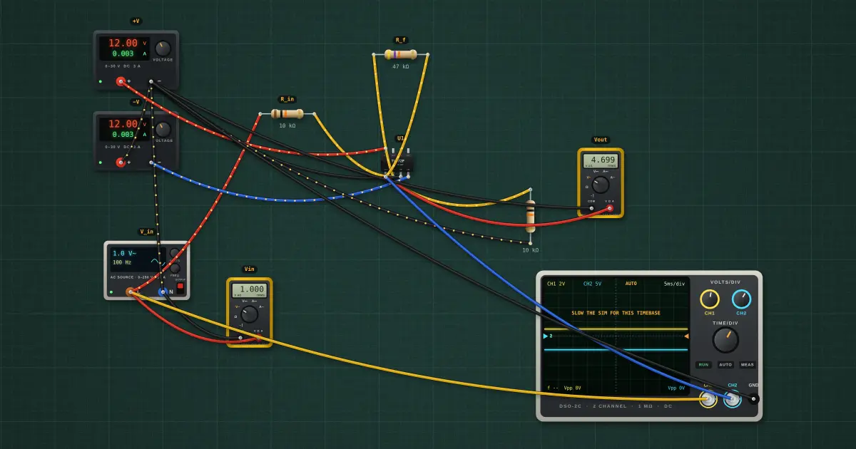
Negative feedback holds the op-amp’s two inputs at the same voltage. With IN+ on ground, IN− becomes a virtual ground, so all of the input current I = V_in / R_in must flow on through R_f: V_out = −(R_f / R_in) · V_in.
Open this lesson in the labFree, in your browser, no account needed.
How it works
Av = −Rf / Rin = −47 kΩ / 10 kΩ = −4.70
Vout = 4.70 × 1 V = 4.70 V RMS, 6.65 V peak, inverted (180°)
The TL072 swings to about ±10.5 V on ±12 V rails, so it clips once the peak passes that.
Try it on the bench
- Select R_f and set 100 kΩ: the gain becomes −10 and the 14 V peaks clip flat at about ±10.5 V on the scope.
- Set R_f equal to R_in for a unity-gain inverter.
- Change the part to an LM358 (same pinout). It swings to within 1.5 V of V+ but nearly all the way down to V−, so with R_f at 100 kΩ the clipping turns lopsided. An LM741 has a different pinout and would need rewiring.
Parts on the bench
- 2 × Bench power supply
- AC source
- 3 × Resistor
- Op-amp
- 2 × Digital multimeter
- Oscilloscope
In the course
Zen’s Electronics Design Mastery, module “Op-Amps & Analog ICs”.