LMR33630 buck regulator IC (LMR33630ADDA)
TI LMR33630ADDA · synchronous step-down regulator, both MOSFETs inside · 3.8–36 V in (38 V absolute maximum) · 3 A · 400 kHz · FB 1.0 V · EN 1.231 V · 4 ms soft start · HSOIC-8 (here on an SOIC-to-DIP adapter)
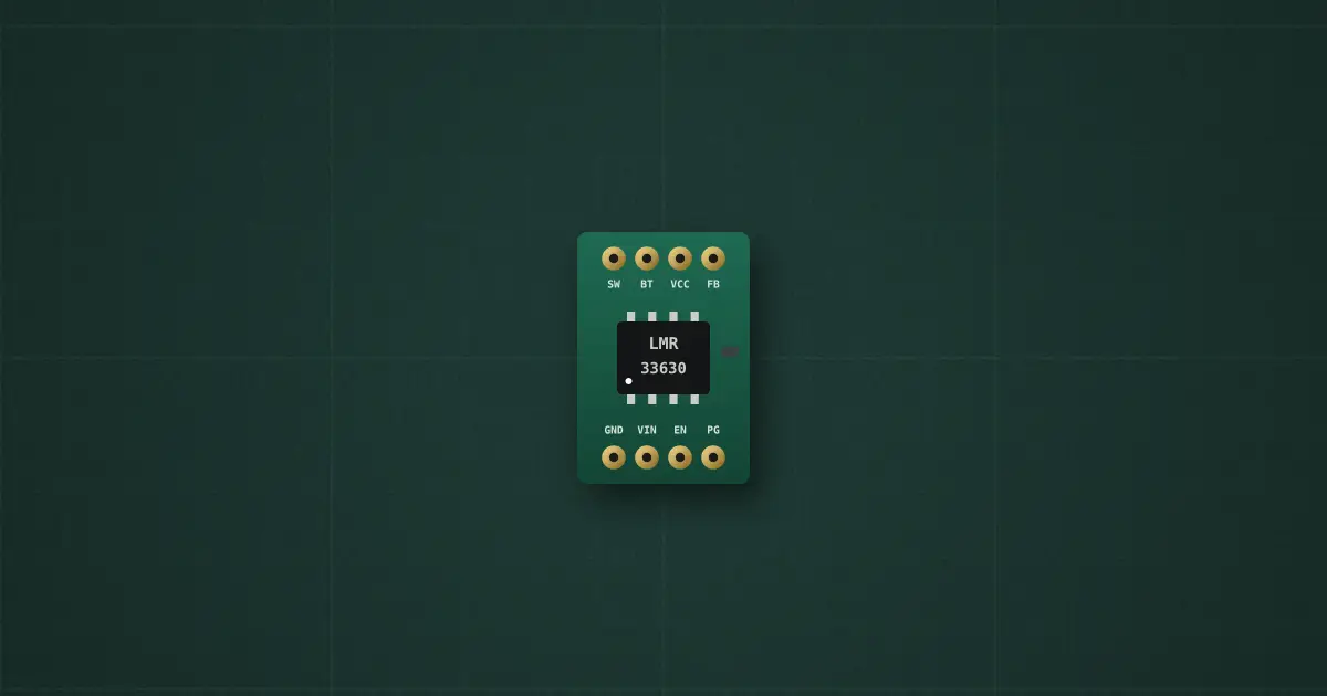
Try it on the benchThe lab drops it on an empty bench and opens its datasheet card.
Typical part: TI LMR33630ADDA, 3.8–36 V 3 A synchronous step-down converter (HSOIC-8)
Pins
- 1 PGND (and the exposed pad)
- 2 VIN
- 3 EN
- 4 PG (power good, open drain)
- 5 FB (1.0 V)
- 6 VCC (5 V, 1 µF to GND)
- 7 BOOT (100 nF to SW)
- 8 SW (to the inductor)
Ratings and limits
| VIN | 3.8–36 V operating · 38 V absolute maximum |
|---|---|
| Output current | 3 A continuous · current limit 4.5 A peak (high side), 3.5 A valley (low side) |
| FB | 1.0 V ± 1.5 % · VOUT = 1.0 V × (1 + RFBT / RFBB) |
| EN | on above 1.231 V, 0.1 V hysteresis · may be tied to VIN · never leave it floating |
| VCC | internal 5 V LDO: 1 µF to GND, no external load |
| BOOT | 100 nF ceramic to SW (high-side driver supply) |
| PG | open drain: low until FB is within 94–107 % · needs a pull-up (100 kΩ to VCC or VOUT) |
| Soft start | about 4 ms |
| Short circuit | hiccup: off 94 ms, retry |
| Thermal shutdown | 165 °C, back on at 148 °C |
| Pins | 1 PGND · 2 VIN · 3 EN · 4 PG · 5 FB · 6 VCC · 7 BOOT · 8 SW · pad AGND (to the ground plane) |
How to use it
Datasheet 5 V / 400 kHz design: 8 µH (8.2 µH) inductor, 4 × 22 µF on the output, 10 µF + 220 nF on the input, 100 kΩ / 24.9 kΩ feedback, 100 nF BOOT, 1 µF VCC.