MAX485 RS-485 module (MAX485CSA, MAX3485)
MAX485 half-duplex RS-485 transceiver module · 5 V part (works at 3.3 V on the bench, out of spec: use a MAX3485 for 3.3 V) · DE high = transmit, RE low = receive (tie them together and drive from one GPIO) · 120 Ω termination fitted · up to 32 drops, 1200 m
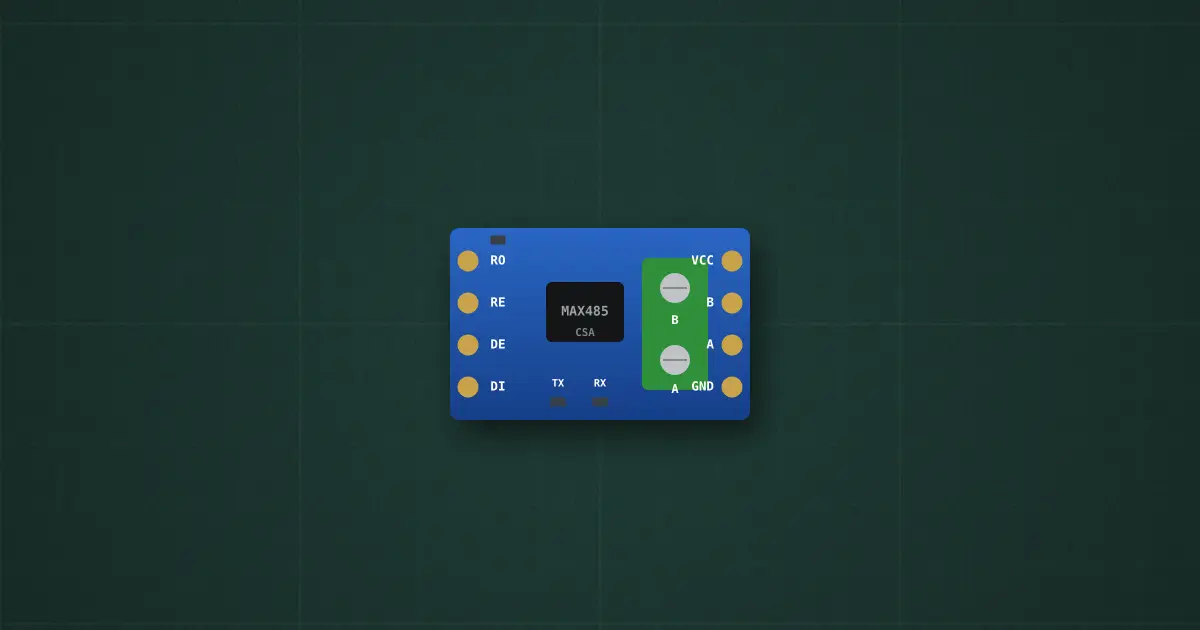
Try it on the benchThe lab drops it on an empty bench and opens its datasheet card.
Typical part: MAX485 TTL ↔ RS-485 module (MAX485CSA / clone, 8-pin header + A/B screw terminal)
Pins
- RO (receiver out → MCU RX)
- RE (receiver enable, active LOW)
- DE (driver enable, HIGH = transmit)
- DI (driver in ← MCU TX)
- VCC
- B (RS-485 −)
- A (RS-485 +)
- GND
Ratings and limits
| Supply | VCC 4.75–5.25 V on the datasheet (absolute maximum 7 V); most clones work at 3.3 V too, with less margin on the bus |
|---|---|
| Direction | half duplex: DE high = the driver talks on A/B; RE low = the receiver passes A/B to RO. Tie DE and RE together to one GPIO: high to send, low to listen |
| Bus | differential: a 1 is A more positive than B by at least 200 mV. Up to 32 unit loads, 1200 m at 9600 baud; twisted pair, the two far ends terminated with 120 Ω |
| Module extras | a 120 Ω terminator (R7) across A/B is already fitted: remove it on modules in the middle of a long bus. 10 kΩ pull-ups on RO, RE, DE, DI |
| Speed | up to 2.5 Mbit/s; Modbus RTU uses 9600–115200 |
| Logic | RO swings to VCC: at 5 V put a divider or a level shifter in front of a 3.3 V ESP32 RX |
How to use it
The bridge between a UART and an RS-485 pair. Wire RO → RX, DI → TX, DE+RE → one GPIO; A to A, B to B on every device (swapped A/B = garbage). With ModbusMaster: node.preTransmission() sets the GPIO high, node.postTransmission() sets it low.
More in microcontrollers & modules
- Arduino Uno R3
- Arduino Nano
- ESP32 DevKit
- ESP32-S3 DevKitC-1
- Raspberry Pi Pico 2
- LILYGO T-SIM A7670E R2
- Orange Pi One
- Coin acceptor
- Coin slot (₱5 only)
- I2C LCD
Sources: Maxim MAX481/MAX483/MAX485 datasheet (19-0122); TIA/EIA-485-A; Modbus over Serial Line Specification V1.02 (RTU framing, 3.5-character gap).