RC low-pass filter
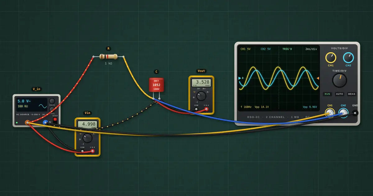
The capacitor’s reactance falls as frequency rises, shorting high frequencies to ground. Below f_c the signal passes; above it the output falls 20 dB per decade and lags by up to 90°.
Open this lesson in the labFree, in your browser, no account needed.
How it works
fc = 1 / (2πRC) = 159.2 Hz
|H| = 1 / √(1 + (f/fc)²) = 0.705 (-3.0 dB) at 160 Hz
φ = −arctan(f/fc) = -45.2°
Try it on the bench
- Select the AC source and type other frequencies: 16 Hz (passes), 160 Hz (−3 dB, −45°), 1600 Hz (about a tenth).
- Compare the yellow input and blue output on the scope. The output lags.
- Open Tools… → Bode plotter and run a sweep: read the −3 dB corner off the curve and compare it with fc in the theory. Change a part and run again; the two curves overlay.
Parts on the bench
- AC source
- Resistor
- Film capacitor
- 2 × Digital multimeter
- Oscilloscope
In the course
Zen’s Electronics Design Mastery, module “AC & Reactance”.