RLC parallel circuit
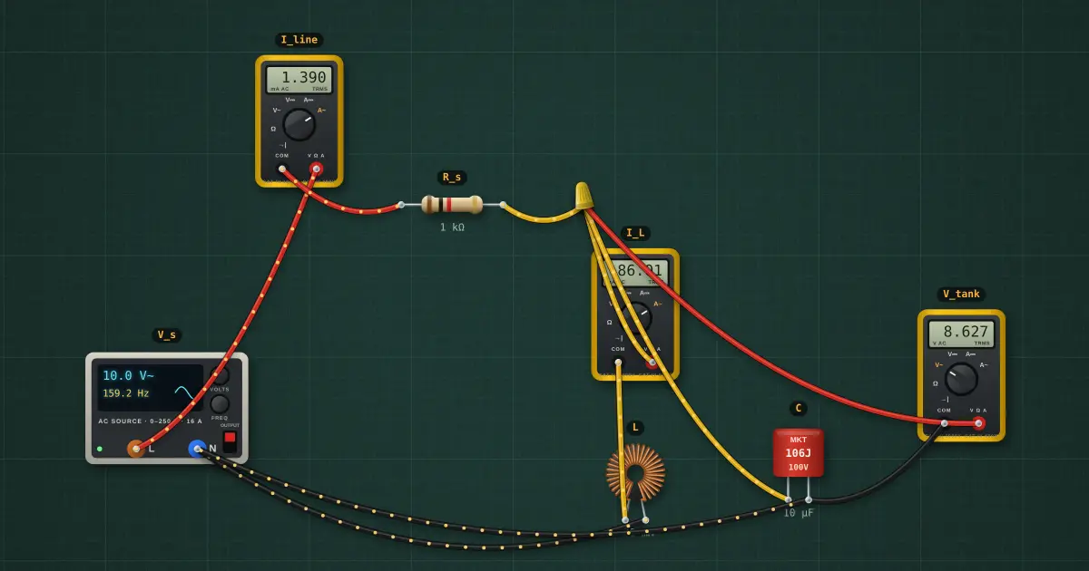
With L and C in parallel, their branch currents are 180° apart. At resonance they cancel in the line, so the tank looks like a large resistor while a big current circulates inside it.
Open this lesson in the labFree, in your browser, no account needed.
How it works
Ztank = ZL ∥ ZC = 6.37 kΩ at 159.2 Hz (resonance at 159.2 Hz)
Iline = Vs / |Rs + Ztank| = 1.357 mA, Vtank = 8.643 V
The coil branch includes its 1.5 Ω winding plus about 0.07 Ω of ammeter and leads; at resonance |Ztank| ≈ L / (rC), so every milliohm counts.
Inside the tank: IL = 86.42 mA, IC = 86.42 mA. At resonance they are far larger than the line current.
Try it on the bench
- At 159 Hz the line current dips to about 1 mA while about 87 mA circulates between L and C.
- Detune to 100 Hz or 250 Hz: the tank impedance collapses and the line current rises.
- Open Tools… → Bode plotter with the output across R: the peak is the resonant frequency and its width gives Q.
Parts on the bench
- AC source
- 3 × Digital multimeter
- Resistor
- Toroidal inductor
- Film capacitor
In the course
Zen’s Electronics Design Mastery, module “AC & Reactance”.