Single-phase AC circuit
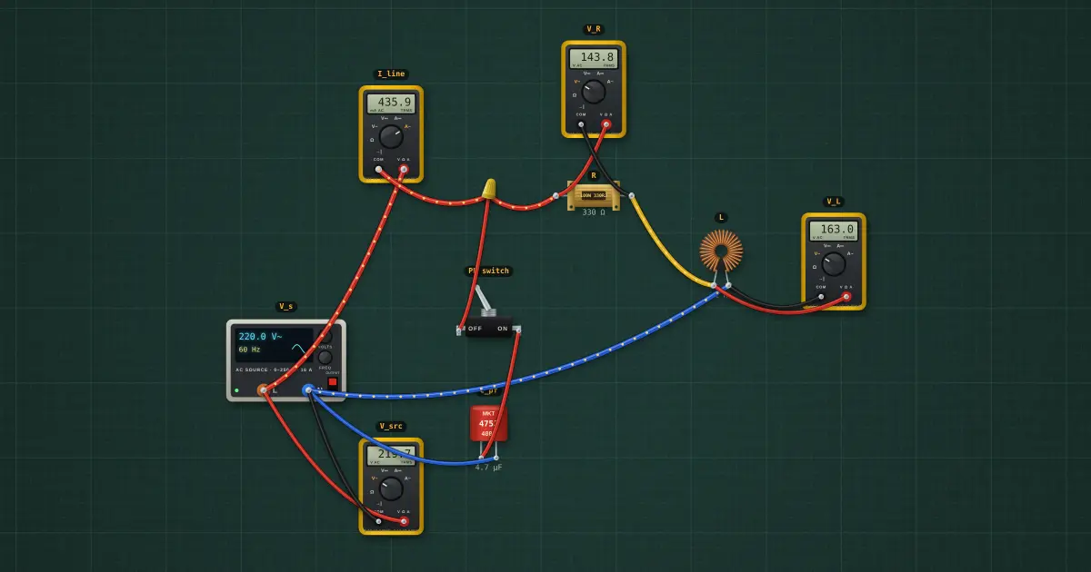
A resistor and an inductor on 220 V mains. The voltages across them do not add arithmetically because they are 90° apart. Only the resistive part consumes real power, and a capacitor can correct the power factor.
Open this lesson in the labFree, in your browser, no account needed.
How it works
Z = (R + rcoil) + jXL = 338 Ω + j377 Ω → |Z| = 506 Ω ∠48.1°
I = V/|Z| = 434.5 mA. P = I²R = 63.8 W, S = V·I = 95.6 VA, Q = 71.2 var
Power factor = cos φ = 0.668 lagging. VR² + VL² = Vs², not VR + VL = Vs.
Try it on the bench
- Note V_R + V_L is well over 220 V. The two are 90° apart, so they add as a right triangle.
- Close the PF switch. The capacitor supplies the reactive current, the line current falls and the power factor rises toward 1, while the real power stays the same.
Parts on the bench
- AC source
- 4 × Digital multimeter
- Resistor
- Toroidal inductor
- Toggle switch
- Film capacitor
In the course
Zen’s Electronics Design Mastery, module “AC & Reactance”.