RLC series circuit
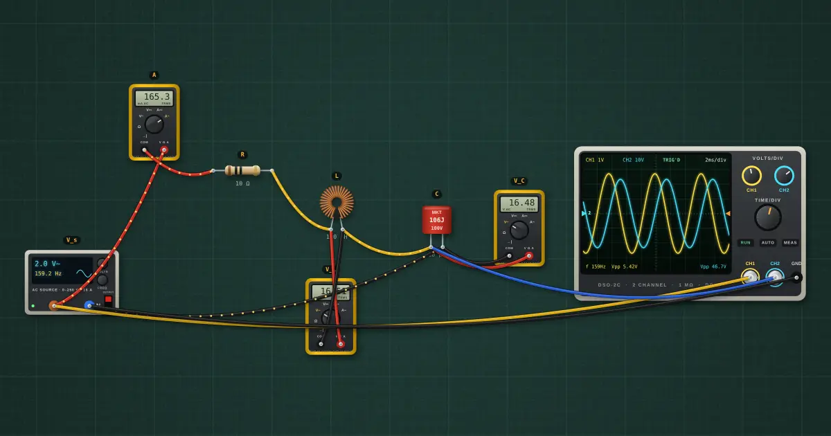
X_L rises with frequency while X_C falls. Where they are equal they cancel: the impedance drops to just R, the current peaks, and V_L and V_C can each be many times the supply.
Open this lesson in the labFree, in your browser, no account needed.
How it works
XL = 2πfL = 100 Ω, XC = 1/(2πfC) = 100 Ω at 159.2 Hz
Z = Rtotal + j(XL − XC), where Rtotal = R + rcoil + 0.5 Ω source + 0.05 Ω ammeter = 12.1 Ω → |Z| = 12.1 Ω, φ = 0.0°
Resonance f₀ = 1 / (2π√LC) = 159.2 Hz. Q = XL/Rtotal = 8.3
Try it on the bench
- At 159 Hz the circuit is at resonance: 2 V in, about 17 V across C. Try 100 Hz and 250 Hz.
- Raise R to 100 Ω. The peak flattens because Q drops.
- Open Tools… → Bode plotter with the output across R: the peak is the resonant frequency and its width gives Q.
Parts on the bench
- AC source
- 3 × Digital multimeter
- Resistor
- Toroidal inductor
- Film capacitor
- Oscilloscope
In the course
Zen’s Electronics Design Mastery, module “AC & Reactance”.