TVS, polyfuse and protection front end
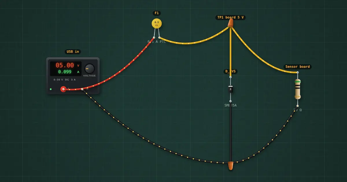
A USB-powered sensor board protects itself with two parts. The TVS diode across the input does nothing at 5 V but clamps anything above about 6.4 V; the polyfuse in series heats up and goes high-resistance when that clamp current flows, then resets when the fault is removed.
Open this lesson in the labFree, in your browser, no account needed.
How it works
Normal: the polyfuse’s 600 mΩ drops a little, so the board gets 5 × 50 ÷ (50 + 0.60) = 4.941 V; the TVS (stand-off 5 V) leaks almost nothing.
At 12 V the TVS conducts amps and clamps the board near 4.9 V (its data-sheet clamping voltage, 8.1 V, is at the full 600 W pulse); that current trips the polyfuse in a second or so, and the board then sees almost nothing.
Try it on the bench
- After the fault, set the supply back to 5 V: the polyfuse stays tripped until power is removed for a few seconds.
Parts on the bench
- Bench power supply
- Resettable polyfuse
- TVS diode
- Resistor
In the course
Electronics Technician, module “Batteries, chargers and USB”.