Buck converter from parts
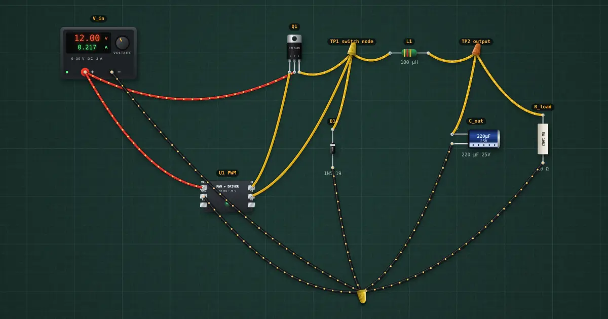
A MOSFET chops 12 V on and off fifty thousand times a second; the inductor and capacitor average the chopped wave. The output is the input times the fraction of time the switch is on (the duty cycle), and almost no power is wasted on the way.
Open this lesson in the labFree, in your browser, no account needed.
How it works
Ideal: V_out = D × V_in = 0.45 × 12 V = 5.40 V.
With the diode drop while the switch is off (0.42 V) and the coil’s resistance: 4.99 V.
Inductor ripple ΔI = (V_in − V_out)·D ÷ (L·f) = 614 mA peak-to-peak; the load draws 499 mA, so the coil current never reaches zero (continuous mode).
Try it on the bench
- Turn the duty cycle up and down on U1: the output follows D × V_in.
- Raise R_load to 100 Ω and watch the coil current touch zero (discontinuous mode).
Parts on the bench
- Bench power supply
- PWM controller + gate driver
- N-channel MOSFET
- Schottky diode
- Axial choke
- Electrolytic capacitor
- Resistor
In the course
Electronics Engineering, module “Diodes and supplies”.