Charge-pump inverter: a negative rail
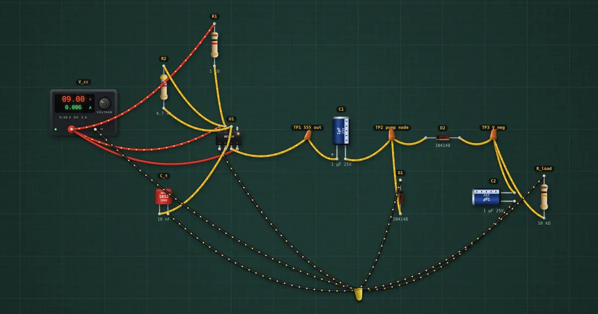
No inductor at all: a 555 square wave charges C1 through D1 while its output is high, then, when the output drops, C1’s bottom plate is pushed below ground and dumps its charge into C2 through D2. The result is a negative voltage almost as big as the square wave, for a few milliamps.
Open this lesson in the labFree, in your browser, no account needed.
How it works
The 555 swings from about 0.1 V to V_CC − 1.7 V = 7.3 V at 13.8 kHz. Each cycle loses two diode drops (0.60 V each) and the load drains I ÷ (f·C) = 64 mV:
V_neg ≈ −(7.3 − 0.1 − 2 × 0.60 − 0.06) = -5.94 V.
Try it on the bench
- Change R_load to 1 kΩ: the rail sags as the capacitors cannot refill fast enough.
- Double C1 and C2: the droop halves.
Parts on the bench
- Bench power supply
- 555 timer
- 3 × Resistor
- Film capacitor
- 2 × Electrolytic capacitor
- 2 × Signal diode
In the course
Electronics Engineering, module “Diodes and supplies”.