Transfer functions and poles
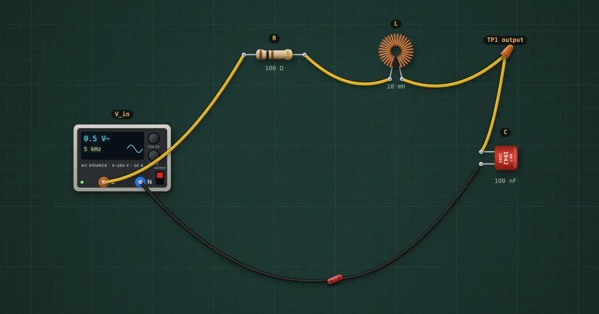
A series R–L–C driving its capacitor is a second-order low-pass: H(s) = 1 ÷ (LCs² + RCs + 1). Its two poles sit where the denominator is zero. With little resistance they are a complex pair close to the jω axis and the response peaks near f₀; with more resistance they split onto the real axis and the peak disappears.
Open this lesson in the labFree, in your browser, no account needed.
How it works
ω₀ = 1 ÷ √(LC) → f₀ = 5.033 kHz; damping ζ = (R ÷ 2)·√(C ÷ L) = 0.159 (Q = 3.15).
Poles at s = −ζω₀ ± ω₀√(ζ² − 1): a complex pair, −5.01 k ± j31.2 k rad/s.
Peak |H| = 1 ÷ (2ζ√(1 − ζ²)) = 3.193 at 4.905 kHz.
Try it on the bench
- Raise R to 63 Ω, 200 Ω, 632 Ω and watch the poles move from complex to real (ζ = 1 at 632 Ω).
Parts on the bench
In the course
Electronics Engineering, module “Filters and frequency response”.