Checking components before installation
Read the ratings of modules, controllers, batteries and inverters, test them before they go on the roof or the wall, and judge whether each one meets the specification. A faulty part found on the ground costs minutes; found after installation it costs a day.
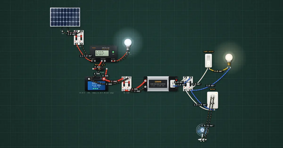
Open this lesson in the labFree, in your browser, no account needed.
How it works
The module nameplate
The label on the back of a module gives its electrical ratings at Standard Test Conditions (STC): irradiance 1000 W/m², cell temperature 25 °C and an air mass of 1.5 (AM1.5, a standard sunlight spectrum). Real conditions are rarely exactly STC, so the numbers are a reference, not a promise.
| Rating | Meaning |
|---|---|
| Pmax | Maximum power at STC, in watts |
| Voc | Open-circuit voltage: no load connected |
| Isc | Short-circuit current: terminals joined through an ammeter |
| Vmp, Imp | Voltage and current at the maximum power point; Pmax = Vmp × Imp |
| Temperature coefficients | How much Pmax, Voc and Isc change per °C away from 25 °C |
| Maximum system voltage, series fuse rating | Limits for strings and protection |
Check that the model and ratings match the design and that every module in a string has the same rating. The IV curve and temperature lessons explain how these numbers move with light and heat.
Testing a module in the sun
With the module disconnected and facing the sun, measure Voc across its terminals with a multimeter, then Isc with a DC clamp meter or a meter rated for the current (follow the meter's instructions; a short across a module is safe only with the right meter and leads, and must be broken with the current stopped, never by pulling a connector under current).
Judge the results against the conditions:
- Isc is roughly proportional to irradiance. At about 800 W/m² expect about 80 % of the nameplate Isc. A reading far below what the sunlight should give points to dirt, a damaged cell or a fault.
- Voc depends little on irradiance (it is near its full value even in fairly weak light) but falls as the cells get hot. A module in tropical noon sun runs well above 25 °C, so expect Voc somewhat below the nameplate. A Voc far below the nameplate (for example, about a third missing) can mean a failed bypass diode or a damaged cell string.
- Compare modules of the same model side by side, in the same sun, at the same time. A module that differs clearly from the others is the one to look at.
Charge controller
Check its ratings against the design: system battery voltage (12, 24 or 48 V), maximum PV input voltage (the cold-morning string voltage must stay under it), maximum charge current, load output current, and type (PWM or MPPT). Then check the settings against the battery's datasheet, not the controller's defaults:
- Absorption (or boost) voltage: the charging voltage held near full charge.
- Float voltage: the lower voltage that keeps a full lead-acid battery topped up. Many LiFePO4 makers ask for a low float or none.
- Low-voltage disconnect (LVD): the voltage at which the load output cuts off to protect the battery, and the reconnect voltage.
- Battery type and temperature compensation: lead-acid charging needs temperature compensation; LiFePO4 usually does not, but must not be charged below about 0 °C unless the battery says it can.
Write the values from the battery's datasheet next to the controller's settings. If they disagree, the battery's datasheet wins.
Battery
The open-circuit voltage after the battery has rested (no charge or load for several hours) gives an idea of its state of charge. A typical 12 V lead-acid battery reads about 12.7 V full, about 12.2 V at half charge and about 11.9 V or less when nearly empty; check the maker's table.
For flooded lead-acid cells, a hydrometer gives a better picture. It measures the specific gravity of the electrolyte in each cell: about 1.265 to 1.280 for a fully charged typical flooded cell, falling to about 1.120 when discharged. Exact values depend on the battery, so use the maker's figures. Temperature affects the reading (warm electrolyte reads lower), so correct using the maker's table. Cells that differ clearly from the others point to a weak cell. Wear goggles and gloves; this is acid.
A LiFePO4 battery has a very flat voltage curve. A 12.8 V (four-cell) pack rests at about 13.3 to 13.4 V when full and sits around 13.0 to 13.2 V over most of its range, then drops quickly near empty. Voltage alone is a poor guide to its charge; use the BMS or battery monitor reading if there is one. On delivery, check that it is in its storage charge range, the BMS responds, and the case is not swollen or damaged.
Inverter
- DC input voltage: must match the battery system (a 12 V inverter on a 24 V battery will be damaged).
- Continuous rating: at least the total of the loads that run together.
- Surge rating: motors, fans, pumps and refrigerators draw several times their running current for a moment when they start. The surge rating must cover that.
- Output: voltage and frequency (230 V, 60 Hz in the Philippines; 120 V/60 Hz or 230 V/50 Hz elsewhere) and waveform. A pure sine wave suits all loads; a modified sine wave can make motors run hot and some electronics misbehave.
Lamps
Check that lamps are the voltage and wattage specified. Where the design gives a lighting level, light a sample and measure with a lux meter at the working height. A lamp that gives clearly less light than its rated output, or flickers, is non-compliant.
IP ratings
The IP (ingress protection) code has two digits: the first for solids (0 to 6), the second for water (0 to 9). Equipment outdoors needs a rating suitable for the exposure.
| Code | Meaning |
|---|---|
| IP65 | Dust-tight; protected against water jets from any direction |
| IP67 | Dust-tight; protected against temporary immersion (to about 1 m for 30 minutes) |
Module junction boxes and PV connectors are usually IP65 or better. An indoor controller is often IP20 or similar and must stay indoors.
Visual checks
Look at every component: cracked or chipped glass, bent frames, burnt marks or browning on cells, damaged junction boxes, cut or crushed cables, bent terminals, loose parts inside, swollen or leaking batteries. Damage on arrival goes on the delivery receipt.
Reporting
Record each component's model, serial number, the ratings you checked, test readings with the time and conditions (sun, temperature), and the result: complies or does not comply, with the reason. Non-compliant parts are tagged and set aside, never quietly installed.
On the job
- Nameplates match the design; modules in a string identical.
- Voc and Isc tested in sun and judged against the conditions.
- Controller settings checked against the battery datasheet.
- Battery voltage or specific gravity recorded; case undamaged.
- Inverter input, continuous, surge and waveform checked.
- IP ratings suit the location; damage noted; report written.
Try it on the bench
- Disconnect the panel (open the DC breaker) and measure its open-circuit voltage at 1000 W/m² and at 500 W/m²: the voltage barely changes.
- Clamp the panel cable with the clamp meter while charging, then halve the sunlight: the current roughly halves.
- Click the battery and set its charge to 100 %, 50 % and 10 %, measuring its voltage each time: see how flat the LiFePO4 curve is in the middle.
Parts on the bench
- Solar panel
- 2 × DC breaker
- Solar charge controller
- LiFePO4 battery
- Power inverter
- AC breaker
- 12 V DC LED bulb
- 220 V bulb
- 220 V desk fan
- Wall switch
- Wall outlet
- Fuse
In the course
PV Systems Installation (NC II-aligned), module “5 · Checking PV components”.