Inductive load and the flyback diode
A relay coil is an inductor, and an inductor’s current cannot stop instantly. When the MOSFET switches off, the coil drives its drain as high as it takes to keep that current flowing, until something breaks down. A diode across the coil gives the current a safe path, and the spike shrinks to one diode drop above the supply.
Open this lesson in the labFree, in your browser, no account needed.
How it works
Coil: 400 Ω, 400 mH → on-current I = 12 / 400 = 30 mA, stored energy ½LI² = 180 µJ
With the diode, at switch-off the coil current flows round through D1. The drain only rises to 12 V + VF = 12.75 V and the current dies away with τ = L/R ≈ 1 ms. The relay drops out a little more slowly; that is the trade-off.
Try it on the bench
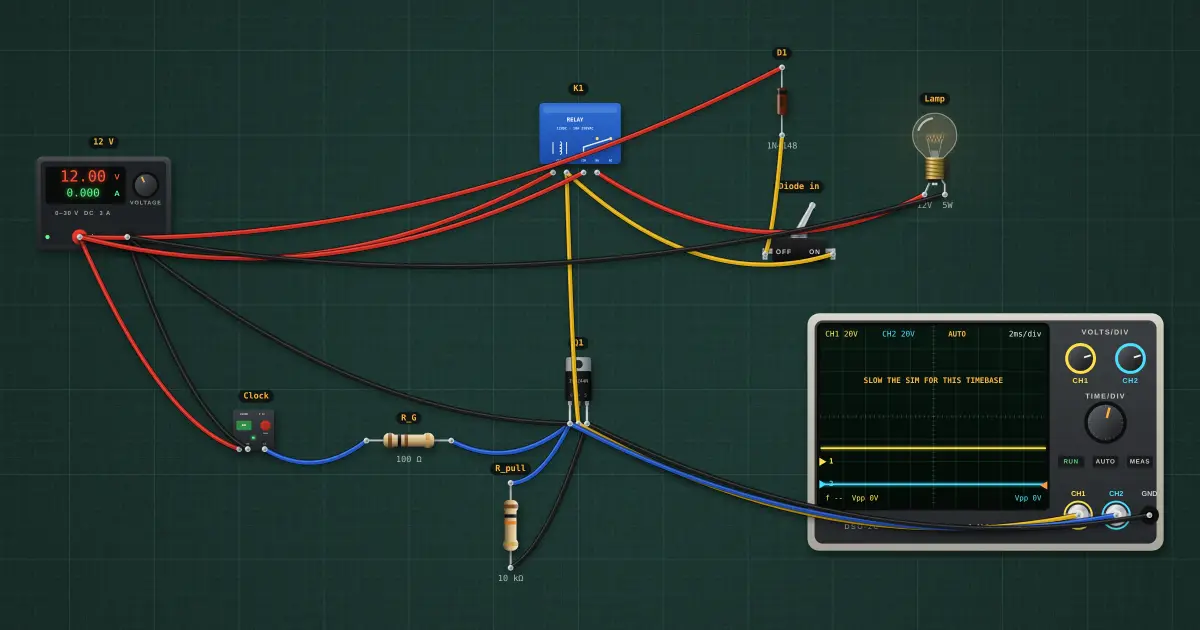
- Watch the scope (yellow = drain, blue = gate). With the diode, the drain rises only to about 12.8 V at switch-off.
- Click the “Diode in” switch off: the drain now spikes to about 55 V, the MOSFET’s breakdown voltage, on every cycle.
- Set the clock to 10 Hz with the diode out and count the avalanche events. A real build would use a 1N4007 across the coil, cathode to +12 V.
Parts on the bench
- Bench power supply
- Clock / pulse generator
- 2 × Resistor
- N-channel MOSFET
- Relay
- Signal diode
- Toggle switch
- Incandescent bulb
- Oscilloscope
In the course
Zen’s Electronics Design Mastery, module “Transistors”.