H-bridge motor driver
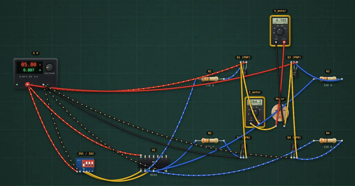
Four transistors around a motor form an “H”. Turning on one diagonal pair drives current through the motor one way; the other pair reverses it. Here each side is a complementary PNP-over-NPN half-bridge whose bases are tied together, so one logic input sets that side high or low.
Open this lesson in the labFree, in your browser, no account needed.
How it works
| IN1 | IN2 | bridge | motor |
|---|---|---|---|
| 0 | 0 | both sides low | brake (motor shorted) |
| 0 | 1 | left low, right high | reverse |
| 1 | 0 | left high, right low | forward |
| 1 | 1 | both sides high | brake |
On each side the inverter drives both bases. A low base turns the PNP on and the NPN off, pulling that motor terminal to 5 V. A high base does the opposite. The bases are tied, so the two transistors on one side can never both be on, which avoids “shoot-through” (except briefly while switching).
Motor voltage ≈ ±(5 − 2 VCE(sat)) ≈ ±4.76 V, current ≈ 781.6 mA.
Try it on the bench
- Flip IN1 and IN2 on the DIP module: the motor runs forward, reverses, or brakes.
- PWM on one input and a steady level on the other gives speed and direction control: that is what an L298N or DRV8833 does.
- Change R1 to 4.7 kΩ: Q1 no longer saturates, the motor voltage drops and Q1 heats up.
Parts on the bench
- Bench power supply
- DIP switch module
- 74xx04
- 4 × Resistor
- 2 × PNP transistor
- 2 × NPN transistor
- 2 × Digital multimeter
- DC motor
In the course
Zen’s Electronics Design Mastery, module “Transistors”.