Push-pull output stage
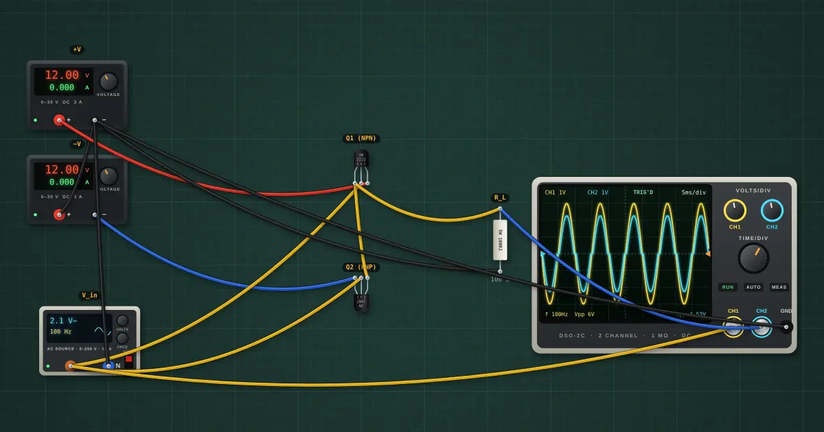
An NPN emitter follower can only push current out and a PNP one can only pull it in. Put one of each back to back and the pair drives a load both ways, from either rail. That is the output stage of almost every audio amplifier and op-amp. Biased like this (class B), neither transistor conducts while the input is within about ±0.65 V of zero: crossover distortion.
Open this lesson in the labFree, in your browser, no account needed.
How it works
For vin > +0.65 V, Q1 conducts and vout ≈ vin − VBE. For vin < −0.65 V, Q2 does and vout ≈ vin + VBE. In between, both are off and vout = 0.
Output peak ≈ 2.985 V − 735.6 mV = 2.249 V. The flat step where the waveform crosses zero is crossover distortion, worst at small signal levels.
Class AB fixes it by biasing each base about 0.65 V apart with two diodes and resistors, so both transistors idle just on.
Try it on the bench
- Look at the blue output trace: a flat step every time it crosses zero.
- Lower the input to 0.5 V RMS: now the distortion is a large part of the signal.
- Raise it to 7 V RMS: the dead zone becomes a small fraction, which is why class B sounds worst at low volume.
Parts on the bench
- 2 × Bench power supply
- AC source
- NPN transistor
- PNP transistor
- Resistor
- Oscilloscope
In the course
Zen’s Electronics Design Mastery, module “Transistors”.