Grounding, bonding and lightning protection
You will be able to tell system grounding, equipment grounding and bonding apart, explain why a grounding conductor makes a breaker trip on a fault, install and test a grounding electrode, and describe a conventional lightning protection system. Good grounding is invisible when it works and deadly when it is missing.
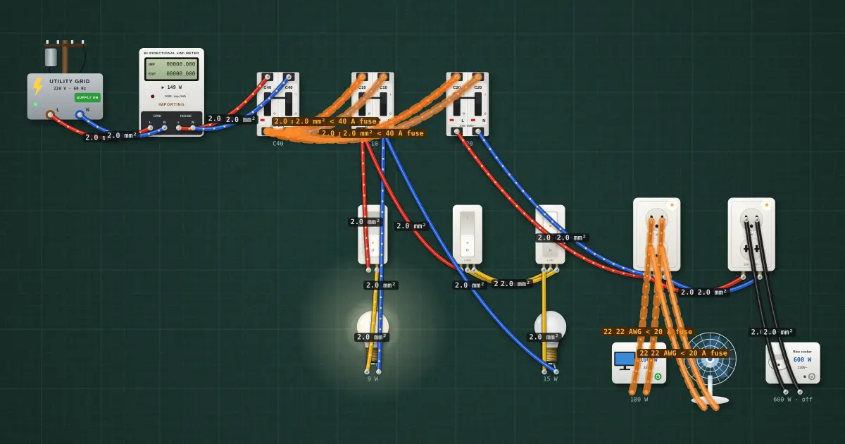
Open this lesson in the labFree, in your browser, no account needed.
How it works
Three ideas that are easy to mix up
| Term | What it means | Why |
|---|---|---|
| System grounding | Connecting one conductor of the supply (the neutral, or a centre point of the transformer) to earth, normally at the transformer and at the service | Holds the system voltage steady relative to earth and limits voltages from lightning and utility faults |
| Equipment grounding | Connecting the exposed metal parts of equipment (metal boxes, appliance cases, outlet ground pins) back to the panel's grounding bar with a grounding conductor | Gives fault current a low-resistance path back to the source so the breaker trips |
| Bonding | Joining metal parts to each other: raceways, boxes, water pipes, structural steel, the lightning system | Keeps all metal you might touch at the same voltage, so no dangerous voltage appears between them |
The rules are in PEC Article 2.50, grounding and bonding (NEC Article 250).
Why the grounding conductor lets the breaker trip
Picture a washing machine whose live wire rubs through and touches its metal case. If the case is connected to the panel by a green grounding conductor, the fault current runs: live wire → case → grounding conductor → panel → back to the source. That path has very low resistance, so the current is hundreds of amperes, and the breaker's magnetic trip opens almost at once. The case was only live for a moment.
Without the grounding conductor, the only path is through the earth, or through the next person who touches the case. The earth has far too much resistance to make a large current flow, so the breaker does not trip and the case stays live. That is the key point: a ground rod alone does not clear a fault. The equipment grounding conductor, run with the circuit wires back to the panel, does. An RCD adds protection on top of this, because it trips on a few tens of milliamps.
On a Philippine line-to-line 230 V service where no grounded conductor is brought to the building, the return path for a fault to ground depends on how the utility's system is grounded, and part of it may run through the earth. That path may not carry enough current to trip a breaker quickly, which is one more reason RCDs are valuable on such services. Follow the grounding arrangement in the plans and the utility's requirements, and never treat a water pipe or a rod by itself as the "ground" for an outlet.
Grounding electrodes
A grounding electrode is the connection to the earth itself. Types the code recognises include a driven ground rod, metal underground water pipe (with a supplementary electrode), the steel reinforcement in a concrete footing (a concrete-encased electrode), a ground ring and buried plates. The plans say which to use.
- A common driven rod is copper-clad steel, typically 2.4 m (8 ft) long, driven fully into the ground so its top is at or below the surface, or protected.
- Where rock stops the rod, the code allows driving it at an angle or burying it in a trench, within limits; follow the code and the plans.
- The connection to the rod uses a clamp listed for direct burial, or an exothermic weld.
Measuring electrode resistance
The resistance from the electrode to the surrounding earth is measured with an earth (ground) resistance tester, using test stakes placed at distances away from the rod, as the tester's instructions describe. A multimeter cannot do this.
The NEC sets 25 Ω as the figure for a single rod: if one rod measures more than 25 Ω, a supplementary electrode must be added. Many job specifications ask for a lower value. Follow the local code and the job spec. If the reading is high, add electrodes (spaced apart so they don't share the same patch of earth; the NEC asks for at least 1.8 m (6 ft) between rods, and wider spacing works better), use longer rods, or follow the designer's method. Soil that is dry, sandy or rocky reads higher, and readings vary with the season.
The grounding electrode conductor (GEC)
The GEC connects the grounding electrode to the service equipment: to the grounding bar, and to the neutral at the service where the system has one. It is sized from a table in the code based on the size of the service conductors. Run it in one continuous length, or with joins made by approved methods, protect it from physical damage, and keep it as short and straight as practical. The bond between the grounded conductor and the grounding bar is made only at the service; downstream sub-panels keep their neutral and ground separate.
Bonding metal pipes and raceways
- Bond the metal water piping and other metal piping that could become energized to the grounding system, using the conductor size the code table gives.
- Metal raceways and boxes must be continuous and tight; use bonding bushings or jumpers where the code requires them, for example around concentric knockouts at the service.
- Bond the structural steel where it is likely to be energized, and bond the lightning protection system to the electrical grounding electrode (see below).
Conventional lightning protection
A lightning protection system gives a strike a safe path to earth so it doesn't pass through the building's structure or wiring. Its parts:
| Part | Job |
|---|---|
| Air terminals (lightning rods) | Metal rods on the roof's high points, ridges and corners that intercept the strike |
| Roof and down conductors | Heavy conductors that link the air terminals and run down the outside of the building by the most direct path, with gentle bends |
| Grounding electrodes | Rods or a ring at the foot of each down conductor that spread the current into the earth |
| Bonding | Connecting the lightning grounding to the electrical grounding electrode system, and bonding nearby metal, so a strike doesn't create a dangerous voltage difference between them |
Lightning protection design follows its own standards, and the plans give the layout. Don't route down conductors through the inside of the building alongside electrical wiring.
SPDs
Lightning protection keeps the building intact; it doesn't stop surges entering on the power and data lines. A surge protective device at the service or panel limits those, and it can only divert a surge if it has a short, solid connection to a good grounding system.
On the job
- Run a grounding conductor with every circuit to every outlet and metal box.
- Drive the electrode fully; connect with a listed clamp.
- Measure with an earth tester; add electrodes if high.
- Neutral-to-ground bond only at the service.
- Bond pipes, raceways and the lightning system to the electrical ground.
Try it on the bench
- With the house bench running, measure each wall outlet from each line terminal to its grounding terminal with the multimeter. On a two-hot service both should read a voltage to ground.
- Run the 🛡 Safety check and look for anything it reports about grounding or bonding.
- Add the SPD at the panel and think about where its ground lead would go in a real panel.
Parts on the bench
- Utility grid
- Net meter
- 3 × AC breaker
- 3 × Wall switch
- 2 × 220 V bulb
- 2 × Wall outlet
- 2 × Household appliance
- 220 V desk fan
In the course
Electrical Installation and Maintenance (NC II-aligned), module “7 · Protective devices, grounding and lightning protection”.