Reading electrical plans
You will be able to read a set of electrical plans: find each outlet, switch and fixture, follow a circuit back to the panel, and read the schedule of loads. Plans are the contract between the designer and the installer, so reading them right saves rework.
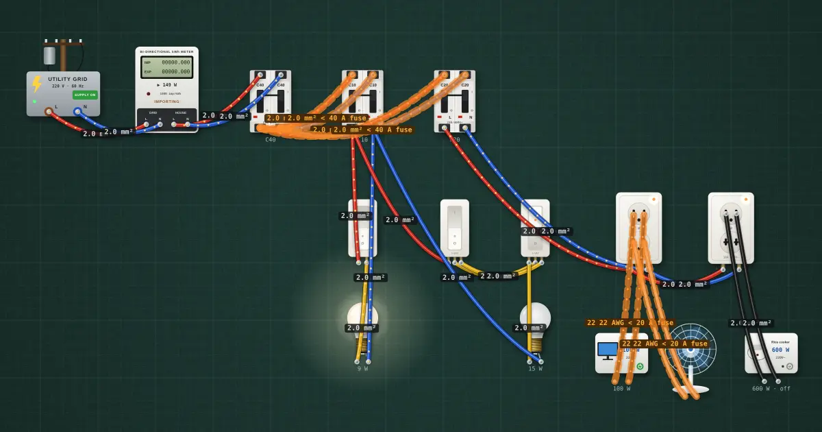
Open this lesson in the labFree, in your browser, no account needed.
How it works
The sheets in a set of plans
| Sheet | What it shows |
|---|---|
| Lighting layout | A floor plan with every lighting fixture and switch, and lines showing which switch controls which fixture. |
| Power layout | Convenience outlets, special-purpose outlets (aircon, water heater, range), and the circuit each belongs to. |
| Single-line diagram | The whole distribution system drawn with one line per circuit: service, meter, main breaker, panelboards, feeders and branch breakers, with wire and breaker sizes. |
| Riser diagram | A vertical view of a multi-storey building: which panel is on which floor and the feeders that rise between them. |
| Schematic / wiring diagram | The actual connections of a control circuit, such as a motor starter or a timer-controlled light, with every wire drawn. |
| Schedule of loads | A table of every circuit in a panel: load, current, breaker, wire and conduit. |
| Legend and general notes | What each symbol means on this job, and rules such as wire type, minimum sizes, mounting heights and the code to follow. |
Always read the legend and notes first. Symbols vary between designers, and the notes often settle questions the layout leaves open.
Common symbols, in words
The shapes below are the ones used by most Philippine and US-style plans. The legend on your plan is what counts.
| Item | Usual symbol |
|---|---|
| Ceiling lighting outlet | A circle, sometimes with a letter for the fixture type |
| Wall-mounted light | A circle with a short line joining it to the wall |
| Fluorescent or linear LED fixture | A long thin rectangle |
| Duplex convenience outlet | A small circle with two parallel lines through it |
| Weatherproof outlet | The outlet symbol with "WP" beside it |
| Special-purpose outlet | A triangle or a circle with a letter (for example "AC" for aircon), as the legend says |
| Single-pole switch | The letter "S" |
| Three-way and four-way switch | "S" with a small "3" or "4" |
| Panelboard | A rectangle, half shaded or with a label such as "LP" or "PP" |
| Junction box | A small circle or square marked "J" |
| Wiring concealed in ceiling or wall | A solid line |
| Wiring concealed in floor | A dashed line |
| Home run to panel | A line ending in an arrow, labelled with the panel and circuit number |
| Number of wires in a run | Short slash marks across the line (often a longer one for the grounding conductor) |
Circuit numbers and home runs
Each outlet or fixture on a layout carries a small number: the circuit it is on. All outlets marked "2" belong to circuit 2 in that panel. The designer draws the wiring from outlet to outlet and ends it with an arrow pointing roughly toward the panel. That arrow is the home run: the length of wire from the last box of the circuit back to the panelboard. It is drawn short only to save clutter; you route it on site along the path the notes allow. A label such as "LP-2" means panel LP, circuit 2.
Slash marks across a run tell you how many conductors are in that piece of conduit. A run with two hot wires, a switch leg and a grounding conductor needs a bigger conduit than a plain two-wire run, and the marks warn you of that.
Reading the schedule of loads
| Ckt | Description | VA | Voltage | Current (A) | Breaker | Wire | Conduit |
|---|---|---|---|---|---|---|---|
| 1 | Lighting outlets, ground floor | 600 | 230 | 2.61 | 15 A, 2P | 2 × 2.0 mm² THHN + 2.0 mm² G | 15 mm PVC |
| 2 | Convenience outlets, living/dining | 1,440 | 230 | 6.26 | 20 A, 2P | 2 × 3.5 mm² THHN + 3.5 mm² G | 20 mm PVC |
| 3 | Aircon, bedroom 1 | 1,800 | 230 | 7.83 | Per plan | Per plan | Per plan |
This is a made-up example to show the columns. VA is the load assigned to the circuit (for outlets, designers often use a fixed figure per outlet, such as 180 VA, under the load-calculation rules of the code). Current is VA ÷ voltage: 600 ÷ 230 = 2.61 A, 1,440 ÷ 230 = 6.26 A. Breaker gives the trip rating and the number of poles (2P on a line-to-line 230 V service). Wire gives the number, size and type of conductors, including the grounding conductor ("G" or "E"). Conduit gives the trade size. The bottom of the schedule totals the load, which sizes the main breaker and feeder. The sizes in the example follow common Philippine practice; on a real job you install exactly what the schedule says.
Scales
Layouts are drawn to scale, written in the title block, for example 1:100 (1 mm on paper is 100 mm on site) or, on US-style plans, a fraction of an inch to a foot. Use a scale ruler, not a normal ruler, and check one known dimension (a room width written on the plan) before measuring others. Prints can shrink or be reduced, so written dimensions beat measured ones. Never scale a single-line diagram or a schematic: they are not drawn to scale.
Checking drawings against the site
- Walk the site with the plans. Are walls, doors and windows where the plan shows them? A door that swings the other way moves the switch.
- Check conflicts with other trades: plumbing, beams, ducts and cabinets.
- Count outlets and fixtures on the layout and compare with the schedule of loads.
- Check the revision number and date in the title block. Work only from the latest issue.
- Write every change on a set of plans kept for the purpose. These marked-up plans become the as-built drawings at turnover.
- If the plan and site disagree in a way that changes a circuit, a breaker or a wire size, ask the supervisor or the designer; don't decide alone.
On the job
- Read the legend and general notes first.
- Find the panel, then trace each circuit number out from it.
- Count conductors from the slash marks before choosing conduit.
- Use written dimensions; check the scale on a known one.
- Latest revision only; mark every change for the as-builts.
Try it on the bench
- Treat the house bench as a small plan: write down which breaker feeds each lamp, outlet and appliance, like a schedule of loads.
- For each circuit, read the load in watts from the parts and work out the current at 230 V (I = P / V). Check your answer with the clamp meter.
- Open each breaker in turn and see which loads go off. Does it match your schedule?
Parts on the bench
- Utility grid
- Net meter
- 3 × AC breaker
- 3 × Wall switch
- 2 × 220 V bulb
- 2 × Wall outlet
- 2 × Household appliance
- 220 V desk fan
In the course
Electrical Installation and Maintenance (NC II-aligned), module “3 · Reading electrical plans”.
More on electrical installation
- Electrical safety, PPE and lockout/tagout
- Hand tools, testers and their care
- Mensuration and electrical calculations
- Splices, terminations and connectors
- Conduit, raceways and boxes: roughing-in
- Wires and cables: types, sizes and pulling
- Panelboards and protective devices
- Grounding, bonding and lightning protection