Splices, terminations and connectors
You will be able to strip a conductor without damaging it, make the standard splices and choose when to use each, and terminate wires on screws, lugs and connectors so they stay tight. Most electrical fires in buildings start at a bad connection, not in the middle of a wire.
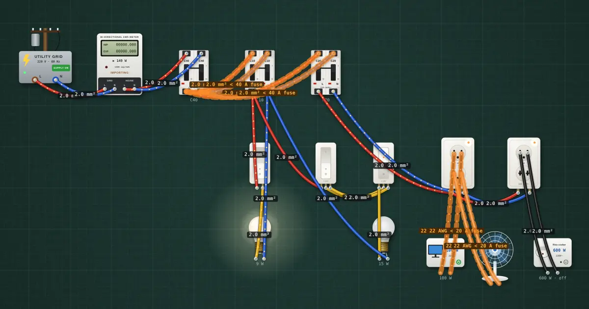
Open this lesson in the labFree, in your browser, no account needed.
How it works
Why connections matter
A loose or poor joint has resistance. Current through resistance makes heat (P = I² × R). The heat oxidises the copper, which raises the resistance, which makes more heat. Over months this can char the insulation and start a fire inside a wall, while the breaker never trips, because the current is normal. A good joint is mechanically tight, electrically sound and insulated at least as well as the wire.
Stripping without nicking
- Use a wire stripper and the notch for the exact wire size. A notch too small cuts into the copper.
- Strip only as much as the joint or terminal needs. Bare copper showing outside a connector or terminal is a shock and short-circuit risk.
- On cable jackets, slit lengthwise with a knife held at a shallow angle, then peel and cut off. Don't ring-cut deep around the jacket: you will score the insulation underneath.
- Check the copper. A nick or ring mark makes a thin spot that heats and can break when the wire is bent. Cut it off and strip again.
- For stranded wire, don't lose strands. Every strand you cut off is copper the circuit was sized for.
The basic splices
| Splice | How it is made | When it is used |
|---|---|---|
| Western Union (long-twist) splice | Two wire ends laid across each other, given a short twist together, then each end wrapped tightly in several turns around the other wire. | Joining two solid wires end to end in a line where the joint must hold tension. A classic training splice; in building wiring, joints are made in boxes instead. |
| Rat-tail (pigtail) splice | The ends of two or more wires held side by side and twisted together, then trimmed and covered with a connector or soldered and taped. | Joining wires that end in a box: the most common splice in building wiring. Also used to make a short "pigtail" to a device so the device can be removed without breaking the circuit. |
| Tap (T) splice | The tap wire's end wrapped tightly around a bared section of a through wire that is not cut. | Taking a branch off a run without cutting it, for example at a junction. |
| Fixture splice | A finer fixture wire wrapped around a heavier branch wire, the end folded back. | Connecting fixture leads to branch circuit wires. |
On a twisted splice, the turns should be tight and close together with no gaps, and the cut ends pressed down so no sharp point sticks out to pierce the tape.
Soldering and taping
- Clean the copper. Make the splice first; solder fills a joint, it doesn't hold it together.
- Heat the wire with the iron and feed electrical solder (rosin core, never acid core) onto the wire, not the iron. It should flow into the turns and look smooth and shiny.
- Let it cool without moving it. A dull, grainy joint ("cold joint") was disturbed or under-heated.
- Tape: start on the insulation about two tape widths back, wrap at a half overlap across the splice and onto the other side, then back again. Use electrical PVC tape rated for the voltage; add a rubber (self-amalgamating) tape layer under it where the job asks for extra insulation or moisture protection.
Connectors
| Connector | Use | Tip |
|---|---|---|
| Twist-on wire connector | Pigtail splices of solid or stranded wire in boxes | Check the box or sheet for the size and number of wires it takes. Twist clockwise until the wires twist together; tug each wire. No bare copper below the skirt. |
| Lever or push-in connector | Splices in boxes, quick fixture connections | Strip to the length marked on the connector; one wire per port. |
| Crimp lug (ring or fork) | Terminating wires on studs and bolted terminals in panels and equipment | The lug must match the wire size and the stud. Crimp with the right die, then pull-test. |
| Ferrule | Finishing stranded wire for screw-clamp terminals (breakers, terminal blocks) | Keeps every strand under the clamp. Crimp with a ferrule crimper; the copper should reach the end of the ferrule. |
| Split-bolt or compression connector | Heavier conductors, grounding connections | Rated for the conductor material and sizes; tighten to the maker's value. |
Terminal screws
- On a binding screw, form a loop with long-nose pliers and hook it clockwise around the screw. Tightening then pulls the loop in, instead of pushing it out.
- Insulation should come close to the screw head, with no long tail of bare copper.
- One wire per screw unless the terminal is marked for two. To connect more, use a pigtail.
- Tighten firmly. Where the device or breaker is marked with a torque value, use a torque screwdriver set to it. Too loose overheats; too tight crushes the wire or cracks the device.
- Stranded wire under a screw clamp: use a ferrule, or twist the strands neatly if the terminal allows it. Don't tin (solder) the end for a screw clamp, as solder slowly flows under pressure and the clamp loosens.
- Use terminals rated for the conductor: copper wire on terminals marked for copper. Aluminium needs terminals and connectors marked for aluminium.
Splices only inside boxes
Every splice and termination must be in a box, fitting or enclosure with a cover, so it stays accessible for inspection and so any heat or arc is contained. Never splice inside a conduit run, inside a wall without a box, or above a ceiling without a box. The box must stay reachable without breaking the building finish.
Testing a connection
- Pull test each wire in a connector or lug.
- Look: no bare copper outside the connector, no nicks, insulation intact.
- Continuity with the circuit dead: the splice should read near zero ohms end to end.
- After energizing, a clamp meter confirms current is flowing; a joint that is warm to the touch (circuit off first) or discoloured has resistance and must be remade.
On the job
- Strip to the right length with the right notch; check for nicks.
- Pigtail splices in boxes, connectors sized for the wires.
- Loops clockwise, one wire per screw, torque where marked.
- Ferrules on stranded wire in clamp terminals.
- Pull test every connection; no splice outside a box.
Try it on the bench
- Measure the voltage at the lamp and at its breaker while it is on. On the bench a good connection gives almost the same voltage at both ends.
- Open a breaker and use the multimeter in continuity mode from the breaker output to the outlet: a sound path reads near 0 Ω.
- Run the 🛡 Safety check after changing any wire on the bench, the way you would inspect a joint before closing a box.
Parts on the bench
- Utility grid
- Net meter
- 3 × AC breaker
- 3 × Wall switch
- 2 × 220 V bulb
- 2 × Wall outlet
- 2 × Household appliance
- 220 V desk fan
In the course
Electrical Installation and Maintenance (NC II-aligned), module “5 · Terminating and connecting”.