Testing and turnover
You will be able to inspect and test a finished installation in the right order, from visual checks and dead tests to live and functional tests, record the results, and hand the job over with complete documents. Testing is how you prove the work is safe before anyone else uses it.
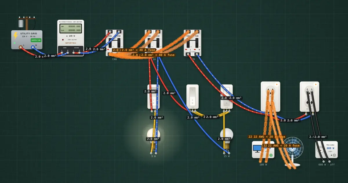
Open this lesson in the labFree, in your browser, no account needed.
How it works
The order of tests
Tests are done in a set order: dead tests first, with the supply off and locked out, then live tests. A fault found by a dead test (a short, a broken ground, bad insulation) is found safely; the same fault found by switching on could cause an arc or a shock.
- Visual inspection
- Continuity of grounding conductors and of circuit conductors
- Insulation resistance
- Polarity (dead check)
- Energize, then live checks: voltage, polarity and grounding at outlets
- RCD tests
- Functional test of every circuit
Visual inspection
- Work matches the plans: every outlet, switch and fixture in place, and circuits as in the schedule of loads.
- Wire sizes, breaker sizes and types as specified; breakers in the right positions.
- All connections tight; no bare copper outside connectors; ferrules on stranded wire.
- Grounding conductors connected at every box, device and fixture, and at the panel bar.
- Covers and plates fitted, no open knockouts in panels and boxes, conduit supported.
- Clear working space in front of the panel; circuit directory filled in.
Continuity tests
With the supply off, use a multimeter or low-resistance ohmmeter on its continuity range.
- Grounding conductor continuity: from the panel grounding bar to the ground terminal of every outlet, and to every metal box and fixture. The reading should be low, a fraction of an ohm to around an ohm depending on length and size. A high or open reading means a broken or missing grounding conductor.
- Circuit conductor continuity: temporarily link the two conductors of a circuit at the panel, then measure across them at each outlet. A low reading proves the circuit is continuous; remove the link afterwards.
- Switches: measure across each switch as you operate it; a 3-way pair should change the lamp circuit from either end.
Insulation-resistance test
The insulation-resistance tester applies a DC test voltage between conductors, and between each conductor and ground, and reads the resistance through the insulation. For 230 V circuits the usual test voltage is 500 V DC.
- Supply off, locked out, proven dead.
- Disconnect or unplug electronics and anything that could be damaged: LED drivers, dimmers, timers, SPDs, RCDs with electronics, appliances, and lamps where practical. The test voltage can destroy them, and connected loads also give false low readings.
- Open lighting switches or link across them so the whole circuit is tested.
- Test line to line, and each line (and neutral if present) to ground.
- Read the value after the reading settles. Afterwards, let the tester discharge the circuit before touching it: long runs store charge.
Acceptance values come from the job specification and the code that applies. A minimum of 1 MΩ at 500 V DC is widely used for low-voltage circuits; a new installation in good condition usually reads much higher. A low reading points to damaged insulation (a nick during the pull, a screw through a wire) or moisture in a box. Split the circuit at boxes to find the section with the fault.
Polarity and grounding checks
- Before energizing: each switch and single-pole breaker is in an ungrounded (live) conductor, never the grounded conductor.
- After energizing, at each outlet measure line to line (about 230 V), each line to ground and, where present, neutral to ground. On a two-hot service, both lines read a voltage to ground. On a system with a grounded neutral, neutral to ground reads near 0 V and the hot reads full voltage to ground.
- A grounding terminal that reads full line voltage to another ground, or a hot that reads 0 V to ground with no load connected, is a fault to find before handover.
- Plug-in outlet testers made for 120 V grounded-neutral systems can mislead on line-to-line 230 V outlets. Use the meter.
RCD test
- Press the test button on every RCD: it must trip. Reset it.
- Where the job spec calls for it, test with an RCD tester, which creates a measured leakage current and records the trip time. The pass values are in the spec and the standard for the device.
- Check that the RCD protects the outlets it is meant to: after it trips, those outlets should be dead.
Functional test of every circuit
Energize circuit by circuit. Switch every light from every switch position. Plug a lamp or tester into every outlet. Run each appliance circuit (aircon, water heater, pump) with its equipment, and measure the current with a clamp meter to compare with the nameplate and the breaker. Open each breaker and confirm it kills exactly the circuit its label says. That last check catches mislabelled circuits, which are dangerous for the next person to work on them.
Labelling
- Circuit directory in the panel matching the actual circuits.
- Main disconnect labelled; panel name and its source.
- Labels on disconnects for equipment, and at junction boxes where the job asks for it.
Turnover documents
| Document | Contents |
|---|---|
| As-built drawings | The plans marked with every change made on site: moved outlets, rerouted runs, changed circuits. |
| Test results | Each test, each circuit, the reading, the instrument used, the date and who tested. |
| Schedule of loads (updated) | As installed, matching the panel directory. |
| Equipment information | Manuals and warranty cards for devices supplied, where the job includes them. |
Notify the supervisor when the tests are complete and give the results. Report any item you could not complete or that failed; don't leave it for someone else to discover. The supervisor or the person in charge decides on energizing and acceptance.
Cleaning up
- Remove scrap wire, conduit offcuts, packaging and dust; vacuum inside panels before closing them.
- Remove your locks and tags only when you are the one who put them on and the circuit is ready.
- Count, clean and return tools; tag any damaged tool.
- Return surplus materials to the store with a list, so they are accounted for.
On the job
- Dead tests before live tests.
- Insulation test at 500 V DC with electronics disconnected; record the values.
- Check both lines to ground on a two-hot service.
- Test every RCD and every circuit; every breaker kills what its label says.
- As-builts, test results, supervisor notified, site clean.
Try it on the bench
- Open each breaker on the house bench in turn and check, with the multimeter, that exactly the outlets and lamps on its circuit go dead. Write a panel directory from what you find.
- With every breaker on, measure each outlet line to line and each line to ground, and record the readings like a test sheet.
- Run the ⏱ Test run and the 🛡 Safety check as your final inspection before "turnover".
Parts on the bench
- Utility grid
- Net meter
- 3 × AC breaker
- 3 × Wall switch
- 2 × 220 V bulb
- 2 × Wall outlet
- 2 × Household appliance
- 220 V desk fan
In the course
Electrical Installation and Maintenance (NC II-aligned), module “9 · Testing, turnover and the final assessment”.